| Home | Contents | Start | Prev | 1 | 2 | Next |
Going Wireless
Avoiding crawling around in the loft space was not the only reason for going wireless, this was a good opportunity to learn something new. I need a mechanism to have a remote switch without wires. It would actually be possible to use a couple of Xbees without microcontrollers to do this. It does seem an overkill to use (relatively) long range wireless to transmit two meters. Besides, I've used Xbees before. I believe this is a great opportunity to learn about Bluetooth and with the peer-to-peer pairing and PIN number, it should be more secure. So Plan-C was to make a remote Bluetooth enabled switch. This will require microcontrollers and it will be a good opportunity to look a low-power sleep mode so the transmitter could be battery powered if necessary. Nothing like excessive technological overkill rather than crawling through the loft!
Bluetooth Modules
I bought two HC-05 Bluetooth modules. These can be configured as master or slave devices. These look a really useful means of getting two devices to talk using a serial interface. I decided to use arduinos as the microcontrollers as they have lots of libraries for serial comms and I know them well. I might experiment with a arduino pro for the transmitter eventually but for now, I'll use UNOs.
Configuring HC-05 Modules
The Bluetooth modules can be configured using a superset of the old Hayes AT command set. After finding all the commands I needed and doing the serial-comms AT configuration dance, I thought there had to be a better way, especially if I ever want to setup Bluetooth modules again for another project. So I wrote a couple of arduino programs. You connect up a module, set the PIN, BAUD, NAME etc and run it. It sets up the slave using AT Commands. Then you flip a Boolean, add the slave address then run it again and it will setup the master and pair the devices. I'll document this in detail in case I need to repeat the process.
Arduino Bluetooth Wiring
As the Bluetooth module is meant to replace a serial connection, it would therefore be possible to use the arduino UART RX and TX pins (hardware serial). However, these pins are used for uploading sketches and as there are lots of pins available, I decided to use SoftwareSerial on different pins to speed up development.
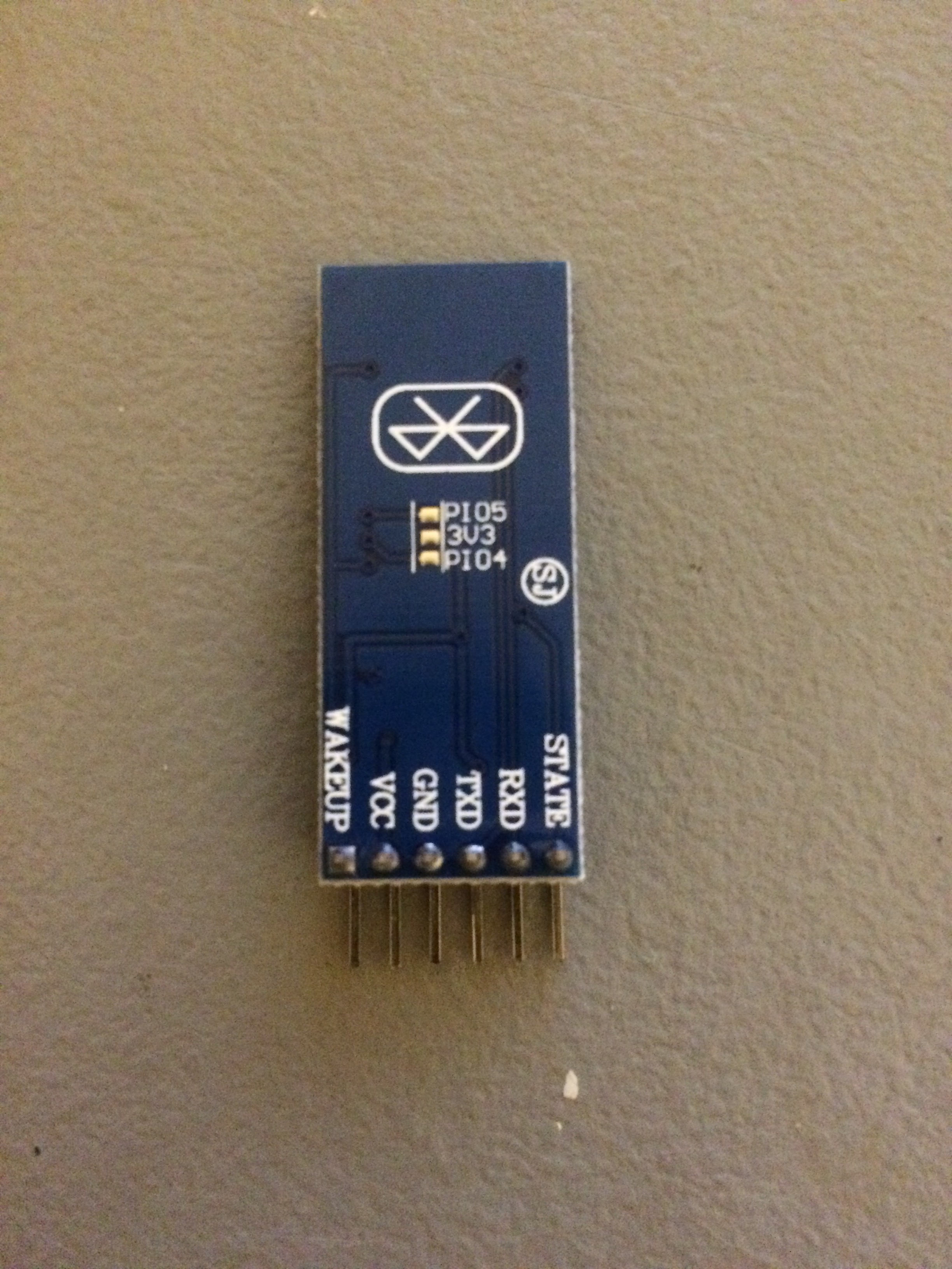
The HC-05 is a 3.3v device and has 6 connections, 4 of which we use in operation and one for setup:
- VCC
- GND
- TX
- RX
- WAKEUP / KEY (used for configuration)
- STATE. (Can be used to power an LED)
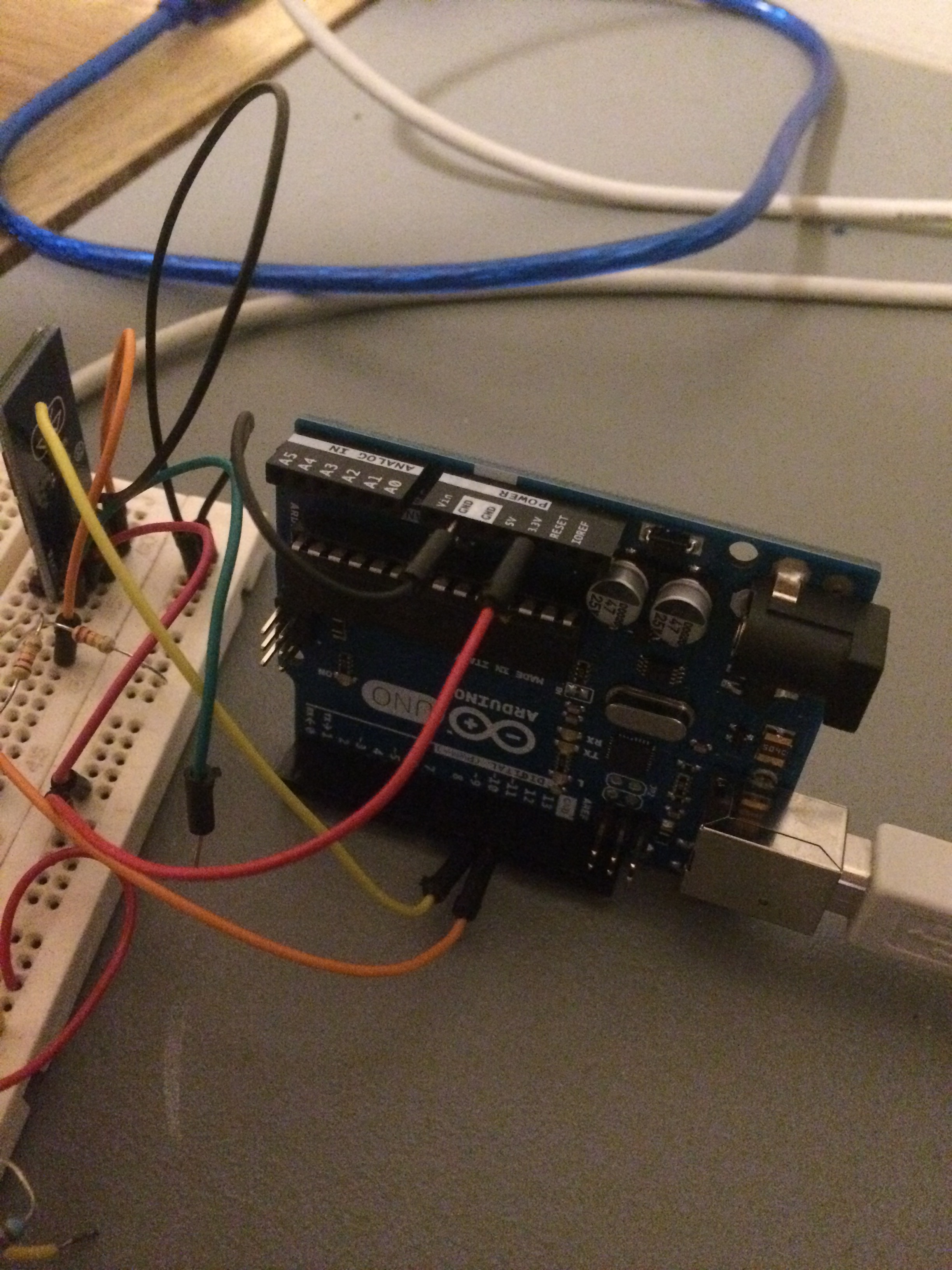
An arduino UNO is a 5V device although it will recognise a 3.3v input as a logic 1 so can be driven by the HC-05 fine. However, we need to be careful that the arduino output is stepped down to 3.3V when it drives the HC-05 via a couple of resistors. This is how I connected the device:

I used pin 10 as Tx and pin 11 as RX when using the arduino SoftwareSerial library.
HC-05 Modes and Defaults
In normal operation the HC-05 is is 'data' mode. To put it into Configuration (AT) mode, the WAKEUP/KEY pin needs to be connected to 3.3v and then turn the power on.
The devices I used have the following defaults:
- AT Configuration mode Baud rate: 38400 bps
- Default name: HC-05
- Default PIN: 1234
- Default data comms baud rate: 9600 bps
You could connect to HC-05 via a serial port and type in all the AT configuration commands (or use the the Arduino serial monitor). Instead, I used the following program (under bluetooth directory in my arduino projects):
/*
Simple setup of HC-05 module and use of SoftwareSerial
Note that the bluetooth module is 3.3v. It will operate on a Vcc of 5v as
it has a voltage converter. However, the Tx output from the arduino will
be 5v and it wont like that. Step it down to 3.3v on this line
*/

/*
  The posible baudrates are:
    AT+UART=1200,0,0 -------1200
    AT+UART=2400,0,0 -------2400
    AT+UART=4800,0,0 -------4800
    AT+UART=9600,0,0 -------9600
    AT+UART=19200,0,0 ------19200
    AT+UART=38400,0,0 ------38400
    AT+UART=57600,0,0 ------57600
    AT+UART=115200,0,0 -----115200
    AT+UART=230400,0,0 -----230400
    AT+UART=460800,0,0 -----460800
    AT+UART=921600,0,0 -----921600
    AT+UART=1382400,0,0 ----1382400
*/

#include <SoftwareSerial.h>

long BAUD_RATE = 38400;
String DEVICE_NAME = "BT_GARAGE";
String PIN = "xxxx";
String COMMS_SPEED = "9600";
boolean SLAVE = false;
String SLAVE_ADDR = "2016,4,000000";      // Note: change colons to commas !

int RX = 10;    // RX on Arduino
int TX = 11;    // TX on Arduino
int KEY = 9;    // KEY on HC-05
// Swap RX/TX connections on bluetooth chip
//   Arduino RX --> Bluetooth TX
//   Arduino TX --> Bluetooth RX (this is the line that requires step-down)
SoftwareSerial mySerial(RX, TX); // RX, TX

void setup() {
  Serial.begin(9600);      // start Serial Monitor for logging purposes.
  pinMode(KEY, OUTPUT);    // We can set this high to enter AT mode. I hardwired it.
  digitalWrite(KEY, HIGH); // we should now be in AT mode.
                           //- this should also have a step-down

  Serial.println("Starting config");
  mySerial.begin(BAUD_RATE);
  delay(1000);

  queryDevice();
  if (SLAVE) {
    Serial.println("Slave");
    setupSlave();
  } else {
    Serial.println("Master");
    setupMaster();
  }

}

void queryDevice() {
  sendCmd("AT\r\n");                //sanity check
  sendCmd("AT+VERSION\r\n");        // Should respond with its version
  sendCmd("AT+NAME\r\n");           // Get current Device Name
  sendCmd("AT+ADDR?\r\n");           // Get Device Address
  sendCmd("AT+PSWD\r\n");           // Get current PIN
  sendCmd("AT+UART\r\n");           // get current comms baud rate
  sendCmd("AT+ROLE\r\n");
}

void setupSlave() {
  Serial.println("Setting the device name");
  sendCmd("AT+NAME=" + DEVICE_NAME +"\r\n");           // Set the Device Name

  Serial.println("Setting the PIN");
  sendCmd("AT+PSWD=" + PIN +"\r\n");                   // Set the pin

  Serial.println("Setting comms speed");
  sendCmd("AT+UART=" + COMMS_SPEED +",0,0\r\n");       // Set the comms link speed

  Serial.println("Setting the role");
  sendCmd("AT+ROLE=0\r\n");                     // set slave mode

  Serial.println("Resetting");
  sendCmd("AT+RESET\r\n");                      // reset after a roll change
}

void setupMaster() {

  Serial.println("Setting the role");
  sendCmd("AT+ROLE=1\r\n");                 // set master mode - may need to restart

  Serial.println("Resetting");
  sendCmd("AT+RESET\r\n");                     // reset after a roll change

  Serial.println("Setting the device name");
  sendCmd("AT+NAME=" + DEVICE_NAME +"\r\n");   // Set the Device Name

  Serial.println("Setting the PIN");
  sendCmd("AT+PSWD=" + PIN +"\r\n");           // Set the pin

  Serial.println("Setting comms speed");
  sendCmd("AT+UART=" + COMMS_SPEED +",0,0\r\n");    // Set the comms link speed

  Serial.println("Clear any paired devices");
  sendCmd("AT+RMAAD\r\n");                          // Clear pairings

  Serial.println("Promiscuous Pairing");
  sendCmd("AT+CMODE=1\r\n");                        // Allow Connecting to ANy Device

  Serial.println("Initialize for pairing.");
  sendCmd("AT+INIT\r\n");                           // Initialize for pairing

   /////// uswful for querying
//  Serial.println("Setting Equiry Options");
//  sendCmd("AT+INQM=0,5,5\r\n");                  // Standard, stop after 5 devices
//                                        found, (or) stop searching after 5 seconds
//
//  Serial.println("Start initialize");
//  sendCmd("AT+INIT\r\n");                             //
//
//  Serial.println("Interogate devices");
//  sendCmd("AT+INQ\r\n");
//
//  Serial.println("Remote name");
//  sendCmd("AT+RNAME? " + SLAVE_ADDR +"\r\n");

  /////// end of useful for querying

  Serial.println("Pair with Slave");
  sendCmd("AT+PAIR=" + SLAVE_ADDR +",9\r\n");   // Pair with slave.
                                                // You must have the set SLAVE_ADDR

  Serial.println("Bind address with Slave");
  sendCmd("AT+BIND=" + SLAVE_ADDR +"\r\n");     // Pair with slave.
                                                // You must have set SLAVE_ADDR

  Serial.println("Only allow PTP pairing");
  sendCmd("AT+CMODE=0\r\n");                    // Only allow pairing with Slave Device

  Serial.println("Make the Link");
  sendCmd("AT+LINK=" + SLAVE_ADDR +"\r\n");     // Create Link with Slave Device

}

void sendCmd(String cmd) {
  Serial.print(cmd);
  mySerial.print(cmd);
  waitForResponse();
}

void waitForResponse() {
    delay(1000);
    while (mySerial.available()) {
      Serial.write(mySerial.read());
    }
    Serial.write("\n");
}

void loop() {
}
Configuration Mechanism
Configuring the module is done like this:
- Connect WAKEUP to 3.3V and turn arduino on.
- Change defaults in the sketch, set SLAVE=true, upload and run it to configure the slave device, while watching the arduino serial monitor.
- If ok, copy the device address from the serial monitor and paste it into the DEVICE_ADDR field in the sketch. Change SLAVE=false.
- Turn off, unplug the module and attach it to a 3.3V USB to serial converter on another USB port and turn it on (WAKEUP not connected -in data mode). To configure the master, the slave must be running. See below for details of this.
- Connect the second module to the Arduino, (CFG mode), turn it on and upload the sketch. It should configure the second module as a master and pair with the first module on the other serial port.
- Disconnect the WAKEUP pin from 3.3v after powering off. It will go into data mode next time.
Connecting the Slave to a Serial Port
For the master to successfully pair, the slave must be up and running (maybe just powered up would do, I've not tried that). This is a requirement for step (4) above. I used a sparkfun FTDI 3.3v USB to Serial converter. This is wired to the Bluetooth module as follows: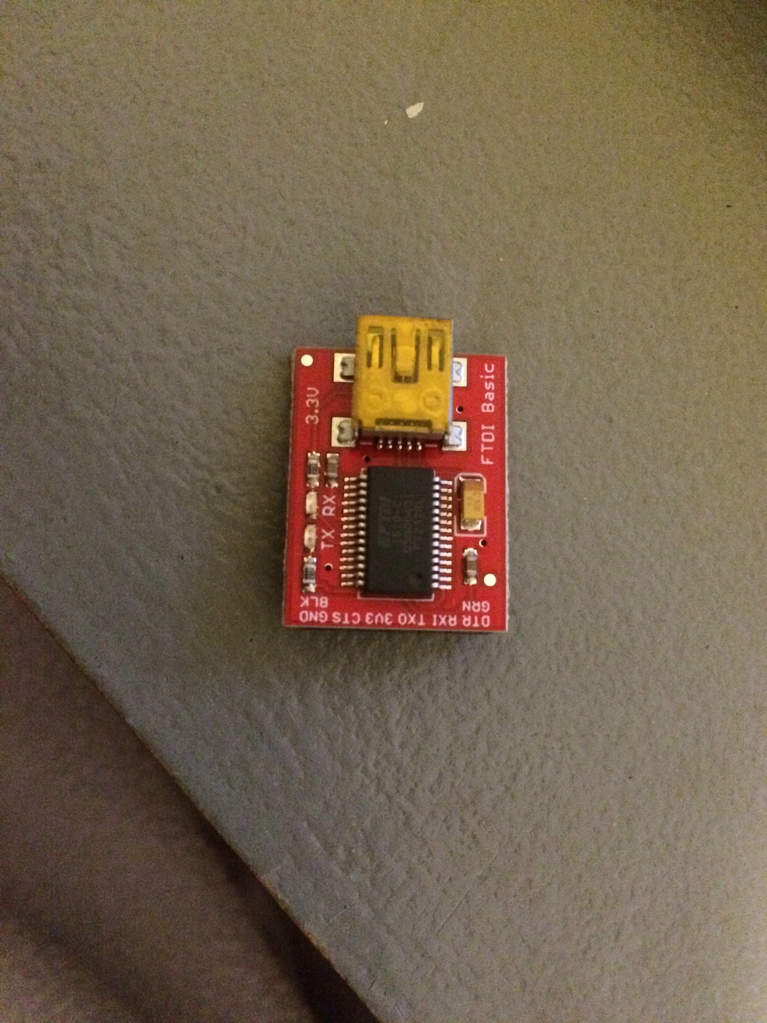
I bought a arduino mini pro (3.3v) and the ftdi board can be easily attached and programmed as normal after selecting the appropriate options from the arduino IDE.
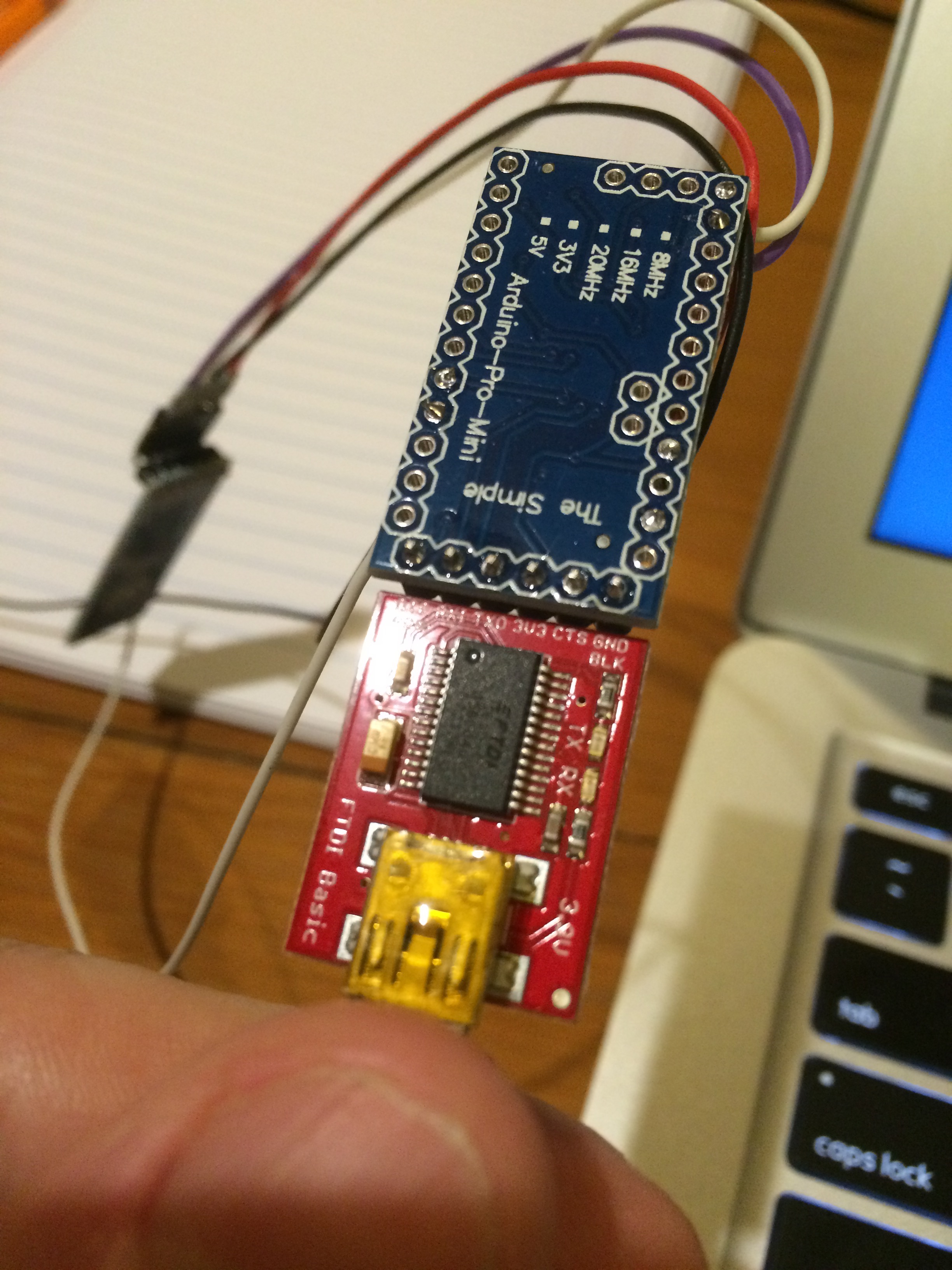
A Uno was used to test the other end.
Note that we are connecting to the HC-05 module in data mode so you need the terminal to use the data mode setting (9600 by default in the setup program). There is no need for voltage conversion as the Serial converter is a 3.3V device.
Testing the Data Connection
To test the data connection, ensure the WAKEUP pin is disconnected from 3.3v on the arduino (master) device. Then upload this program:
// Bluetooth Client Test

#include <SoftwareSerial.h>

int RX = 10;    // RX on Arduino
int TX = 11;    // TX on Arduino

// Swap RX/TX connections on bluetooth chip
//   Arduino RX --> Bluetooth TX
//   Arduino TX --> Bluetooth RX (this is the line that requires step-down)
SoftwareSerial mySerial(RX, TX); // RX, TX

void setup() {
  Serial.begin(9600);      // start Serial Monitor for logging purposes.

  mySerial.begin(9600);
  delay(1000);
}

void loop() {

if (mySerial.available())
  Serial.write(mySerial.read());

if (Serial.available())
  mySerial.write(Serial.read());
}
Power up and the master should pair and link with the slave device which is running on the FTDI connection. Ensure the Arduino serial monitor is running at the same data rate as the modules (9600 by default), You should then be able to: Type text in the serial monitor and it should appear in the cool term window. Then type text in the cool term window and it should appear in the serial monitor window.
So now we have a working wireless Bluetooth link, it's time to get on with project in hand, namely being able to unlock my garage side door wirelessly from inside the house. Having two arduinos connected in this manner means that in the future, I could control a whole lot of things in the garage (or even monitor them). However, let's not get distracted from the task in hand.
| Home | Contents | Start | Prev | 1 | 2 | Next |