| Home | Contents | Start | Prev | 1 | 2 | Next |
Construction
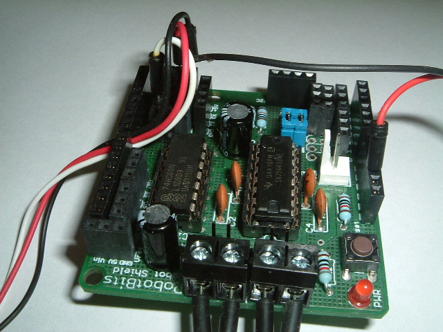
There is no motor-driver chip on the arduino, so I bought a 'motor shield' kit that would plug into the arduino and provide this functionailty. I changed the headers so that another board could be plugged over the shield later (ideally a wireless board).
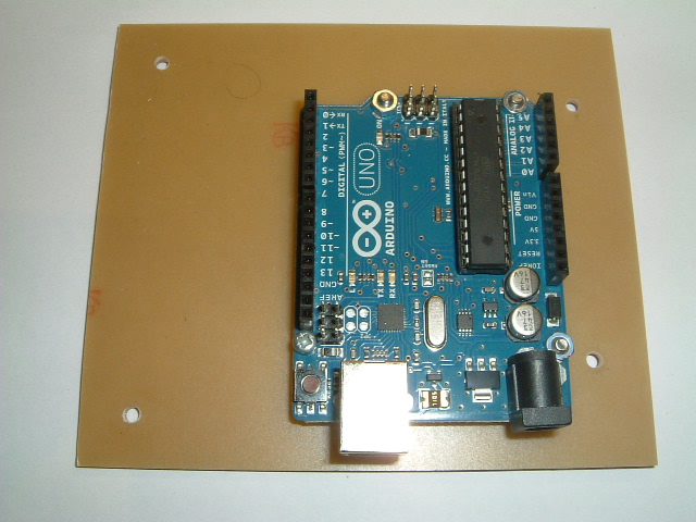
The sandbot was designed so it would be easy to swap out processor boards so I pre-drilled a new blank PCB card so it could replace the old one, and mounted the arduino on it. The arduino uno has a small footprint so I left some space next to it for a general-purpose breadboard/breakout board.
The arduino and motor shield were mounted and the new board put in place on the robot. Wires were connected to the motors and power and then it was time to hit the keyboard to perform some locomotion testing. Now that PWM is available, it should be possible to control the motor speed as well as duration of its on-period so hopefully I should get some extra functionality immediately.
Programming the Arduino
Well this was a revelation. The bundled libraries and simple environment make programming a painless process. I could reproduce all the functionality I had on the PIC platform within a couple of hours. This had taken me forever using a PIC. Admittedly I was writing the libraries themselves, and had thinking time to consider. However, there was no need to consult architecture diagrams, setup registers, flip bits, adjust timer dividers to get appropriate PWM clock-rates. My PIC libraries used interrupts and I note that my arduino code is not, so I assume this is being done in the libraries, just as mine were although the coding process seems more serial on arduino. There must be ways to add interrupts to arduino as I note two pins are dedicate to them but I will investigate this when I need to. Oddly enough, for the PIC system, I needed to know the chip architecture very well whereas the AVR architecture is totally hidden by the arduino APIs. I guess this is one step closer to dealing with navigation algorithms rather than bit flipping so I need to accept the abstraction and only dive into hardware when necessary.
Results
The serial monitor is brilliant, I'm not fumbling around in the dark any longer. I could get the robot to run motors, turn the servo, read from the IR sensor and all the results were fed back to the serial monitor to see what was going on. This made adjusting the IR sensor threshold levels much easier. However, I needed to suspend the robot wheels off the desk to prevent it wandering away. The USB cable tether needed to go, then I could get real-time logging back from the robot as it wanders around the room. So it was time to investigate wireless options. It would be great to be able to wirelessly program but I could live without that. Wireless telemetry is becoming an essential before I can move on. So that was the next task.
Going Wireless
I know I am treading well-worn paths here but sometimes you just need to work things out for yourself. It seemed to me there were three contenders for wireless telemetry, WIFI, bluetooth or RF.
WIFI is tempting option due to the high bandwidth and the fact I already have it in the house. However, WIFI modules for the arduino are expenive and it's a lot of technology considering I will be feeding it into a serial port at the robot end. I may revisit this option if I move up to a more powerful processor but the term overkill comes to mind here.
Bluetooth has a range of 10 metres or so which is more than enough for my needs. Again it is an expensive option and judging by the problems I have had with bluetooth with mice and compters, I don't have a lot of time for it. Maybe I'll come back to this in the future.
Custom RF is a cheaper option and the lower data-rate fits better with my simple requirements. I see Xbee and Zigbee are simple options and have a range similar to WIFI. After consulting with google for a while, it looked like Xbee was the way to go, a Xbee shields exist for the arduino. So this is my preferred option and I may grow into wifi at a later stage.
Configuring Xbee
I bought a couple of Xbee modules, a USB->Xbee adaptor (PC side) and an Xbee shield for the arduino. There seem to be a confusing array of Xbee modules of various power ranges and those suitable for mesh networks. I went for simple point-to-point as that is all that is needed here. There is a configuration program called X-CTU for the xbee which is free to download. Unfortunately, this is windows only but can be run in a VirtualMachine on a Mac with no problems. I'm not really very familiar with windows and soon ended up looking for drivers but the internet is a wonderful thing :-). There are the steps I took to configure each Xbee:
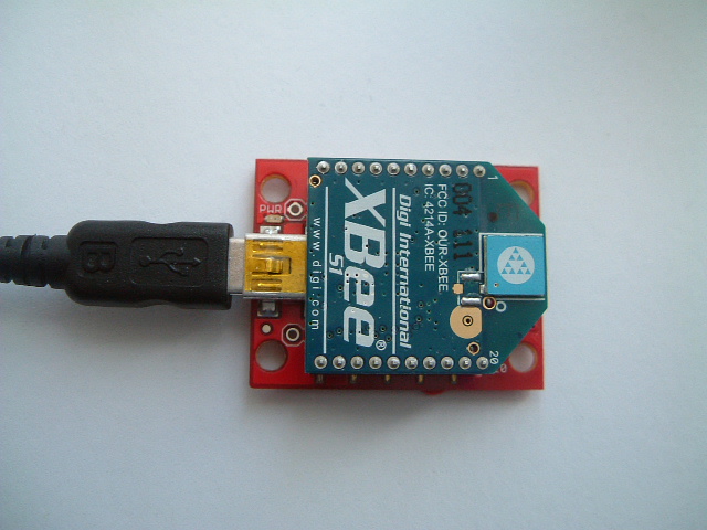
- Connect Xbee to PC via the adaptor board
- Install driver so PC recognizes the adaptor
- Connect to Xbee using X-CTU using 8 bits, no parity, 1 stop bit at 9600 bps
- Set communication speed to 57600 bps
- Set PANID = 4444
One Xbee was used in the shield and the Xbee board sandwiched onto the arduino stack. The other was left in the adaptor and plugged into the USB port of the PC. I am aiming at making the wireless connection transparent so that the computer is unaware that there is not a cable between it and the robot. It took some time fiddling around with drivers for the adaptor (fdti chip) but once those were sorted, it worked fine.
I used an IR-pinger test program to send measurements back via the serial interface and the output comes through on the arduino monitor, totally transparently - Xbees are great :-). I did some simple range tests and the telemetry worked fine over a 6 metre range which is more than I need so am very pleased with the outcome. It was also possible to send the data back to the computer and display it in the terminal using 'screen'.
Out of curiosity, I tried pushing the data rate up to 115200 bps, the maximum the Xbee will support. Although this worked, I noticed that occassionally (about 5% of the time), I read back junk. I assume this is a sync problem and bits were being dropped. With motors and servos running, the robot will be an electrically noisy environment so I think 115200 bps is too high for the data rate, I'd rather have it running slower but more reliably. I returned the data rate to 57600 bps and found I had no telemetry errors at all, even when running over a long period of time.
Xbee Limitations
As expected, I could not program the arduino remotely but then I found a problem. If I try to program via the USB cable, it does not work either. I believe there is bun-fight over the Tx and Rx pins as the Xbee shield is trying to use them at the same time as the USB lead. There is a small switch on the Xbee shield that allows the xbee to be disconnected and USB programming works as before. However, getting access to the switch is not easy once the shield is in the arduino stack so I need a way to be able to program the device without dismantling the hardware first.
There were several ways I could approach this problem.
- The switch leads could be brought out to an external switch.
- The 'switch' could be passed through some external transistors that could be operated by software.
- Find a way to remotely program the arduino.
The first of these options is obviously the easiest although I might just be delaying the problem as the external switch will be tied into the Xbee shield so it breaks the modularity of the system
The second option is better, but unless I can control the transistors via software through the USB cable, it will mean doctoring any running program to allow commands to be sent. This is a horrible solution.
If it were possible to send commands over the Xbee connection to change mode, it makes sense to work out how to do this during the programming phase, in which case, it may be worth going for gold and try and implement remote programming as well. This certainly will be more convenient although I need to read around a bit first.
Remote Arduino Programming using Xbee
The Xbee modules have a neat 'pass-through' feature that allows you to transparently pass logic levels for the corresponding server-side Xbee pin from the client-side Xbee (after suitable configuration). This basically consists of:
- Configuring a pin on the PC Xbee to be an input or output with default value
- Provide a bit-mask so that only the appropriate pin data is passed
- Configure the approriate Xbee (arduino-side) pin and its bit-mask
Doing this, it should be possible to control a bit at the PC end to make the associated arduino-side Xbee pin switch state - all over the Xbee connection.
In order to program the arduino, the first thing that needs to happen is to pull its reset pin low, before the program is uploaded via the serial port. For a serial transmission, the Ready-To-Send (RTS) line goes low to initiate communication. If this signal can be piggy-packed over the Xbee connection, it will start the program cycle immediately afterwards. Fortunately, the RTS signal is available on the client Xbee so it is possible to use the pass-through mechanism to get that signal to the arduino and the arduino then needs to use it to force a reset. The rest of the program should then come down the connection and with a bit of luck and a good headwind, the Arduino bootloader should do the rest.
Configuring the PC-Xbee
The following steps were taken (using X-CTU)
- Configure DIO2 to be a digital input.
- Set bit-mask to be 0x04 so only this pin info is passed over the connection.
- Set packet timeout to be 10 seconds.
Now on the Xbee adaptor board, a wire link was made between the RTS pin and the DIO2 pin. This should mean that the RTS signal is propagated through the DIO2 pin to the Xbee on the arduino.

Configuring the Arduino-Xbee
The arduino-Xbee was removed and put back in the adaptor board for reconfiguration with X-CTU. The following changes were made:
- Configure DIO2 to be a digital output and default to logic 1.
- Set the pass-through to be 0x04.
- Set packet timeout to be 10 seconds.
- Disable DIO2 from outputting to the serial stream.
A wire was soldered onto the Xbee shield from the DIO2 pin and brought out for monitoring. The Xbees were then returned to their appropriate sockets and the connection brought up again. An oscilloscope was used on the wire connected to the DIO2 pin on the Xbee shield. It remained at logic 1 while the IR-Test program was running on the arduino. Now I tried to upload a programme from the arduino IDE. It failed but I could see the DIO2 ping being pulled down to 0 in sympathy with RTS pin on the PC-Xbee. Progress indeed :-)

In theory, the DIO2 pin on the Xbee shield should just connect to the reset pin on the arduino. However, this did not work so I added a small driver transistor to give it some assistance in resetting the chip. However, I could still not get the program to upload.
I'v hit a bit of an impass here. Returning to the USB cable, I turned on verbose debugging and note that the arduino uploads at 115200 bps using a program called avrdude. If I run the same program from the command line, it works fine over the USB connection. I tried programming at 57600 bps but this fails. So it seems the arduino upload is optimized for 115200 bps, as fast as possible. This means that my Xbee connection which is set at 57600bps will not allow upload. I have tried increasing the Xbee data rate to 115200 bps but found the commincation was unreliable. So, arduino wants 115200 but xbee is happy with 57600. It is possible the bootloader only works at 115200bps so it may be necessary to use a different bootloader for lower upload speeds. At this stage, it is not really a burning issue. Perhaps when I become more familiar with the details of the arduino, I can investigate this issue. For now, I think I'll revert to plan-A and use a switch.
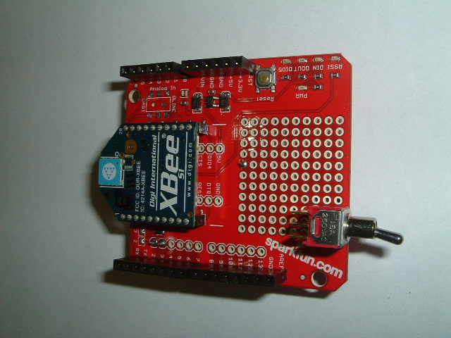
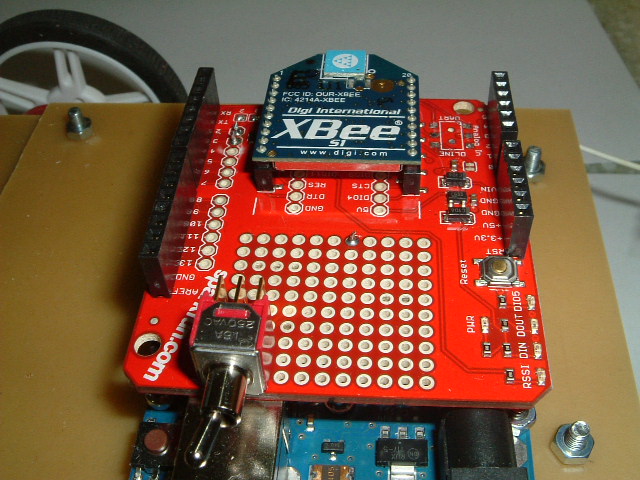
Modifying the Xbee Shield
The Xbee shield I use comes from sparkfun. It has a small DPDT switch that allows the DOUT and DIN pins on the Xbee to be switched to Rx,Tx or D2,D3 on the arduino. This is a small surface-mount switch which is hard to get at once the shield is put into the arduino stack. There is a small prototyping area on the board and I reasoned I could mount a minature toggle switch here and replace the one on the board. Getting the small switch off the board with a heated spade proved tricky and I could not use the original solder pads but luckily there are enough places on the board from which to pull the appropriate signal. The result is shown below. The switch sits just above the USB port and is flipped one way for USB programming, then the other for wireless operation.
| Home | Contents | Start | Prev | 1 | 2 | Next |