| Home | Contents | Start | Prev | 1 | 2 | 3 | 4 | 5 | 6 | 7 | 8 | 9 | Next |
Chassis and Blade Height Revisited
Well, its a year since I have had the opportunity to work on this project so its time to get on with it again. From my previous investigations, I had found a suitable blade arrangement although the chassis and blade height needed revisiting.
I had used a plywood base before but apart from it having the potential to rot, it did not seem suitable for mounting motors etc on and lacked the accuracy of metal. I decided to try a few different plastics as I have not really worked with these materials. The candidates I looked into were:
- HDPE (High Density PolyEthyline)
- PVC
- Perspex
HDPE was the cheapest option. It is very easy to work and has a reasonable flex. It does not glue too easily however. I felt that it was not rigid enough for this application although would be ideal for a smaller indoor robot.
Both PVC and perspex were rigid and were suitable for a platform. I decided to use PVC as it was slightly softer and I know is easy to glue and drill. Hopefully it will be less brittle if exposed to sunlight although I suspect all plastics suffer from that to some extent.
Although a four wheel design may be more stable, a two-wheel + castor design is easier to control and manufacture so I set about designing such a chassis. I have found in the past that a circular design is ideal as the robot can turn in its own footprint. However, in this case I decided to have a chassis with corners as it gave some degree of protection from the cutting blade and there are less obstacles to deal with in a garden compared to an indoor environment.
Wheels revisited
When looking into blade height earlier, I was amazed at how high you need to have the blade from the ground due to ruts and bumps on the lawn. To my eye, the lawn looks relatively flat, it's not a bowling green but when you get your head down to a robot-eye view, it does resemble a grassy moonscape. With this in mind, I decided to go for rather large wheels as these have less chance of getting stuck and also raise the chassis higher off the ground. After looking about, I found Banebot wheels and chose the large 128mm wheels. Banebot wheels have a versatile adaptor for attaching them to motor shafts which also gave some degree of flexibility. A wider wheel also gave more stability and you can even choose how 'grippy' the tyres are!.
The larger wheels gave XXXcm of clearance between the bottom of the chassis and the ground which seemed a good place to start. If I need to, it should be possible to make the blade height adjustable (or even chock the motor mounts) but I'd rather avoid this if I can.
With a larger wheel, for a given motor speed, the robot will go much faster. As a mower has a rotating blade, I'd rather it move much more slowly so you can can see it coming so this requires high gearing. High gearing gives a lot of torque which is a good thing when pushing through grass. By choosing wheel diameter and motor speed/gearing a good compromise can be found.
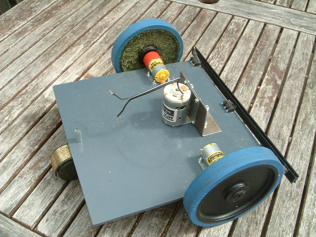
The new PVC chassis.
Mower Locomotion Speed
The wheels used are 128mm in diameter, so in one revolution they will move pi * 128 = 0.4 metres.
The motor being using has an average (load) speed of 7000 rpm and it is driving a 250:1 gearbox. The geared down speed is therefore 7000/250 = 28 rpm.
This gives a speed over the ground of 28 * 0.4 = 11.2 metres/min or 19 cm/sec so it will take approximately 5 seconds to travel 1 metre.
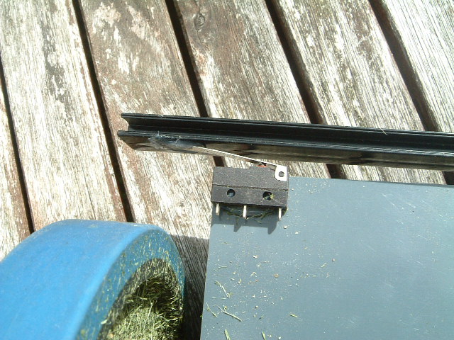
Bump Switches
I mounted two microswitches on the chassis, one in each front corner. This allows for the mower to bump into something at an angle and take different action than if it hits head-on. To give it better coverage, a plastic bar was used to attach the two switches as this gives a larger 'touch area'. The connecting bar needed a small amount of flexibility so the two switches were not locked together and could work together without one adversely effecting the other. To cater for the flex, another microswitch was mounted right in the centre so we have a left, right and head-on collision detection.
Hardware
Pinout resources
The propulsion motors will be driven through an H-bridge to allow for easy steering. This will require 4 Arduino pins, two digital and two PWM.
The front bump sensors will be made up of three microswitches, therefore 3 extra digital inputs are required
The main grass cutting motor must be able to be turned on and off which requires an extra digital output
The battery will need to be switched off from the main power drivers. This is either during charging or when the battery voltage becomes too low. One more digital output.
The battery voltage needs to be monitored. An analogue input will be required
If a solar panel is connected, a light sensor may be required. This would use an analogue input.
So this gives a total of:
- 9 digital i/o pins (includes 2 PWM outputs)
- 2 analogue input pins
- Two extra digital pins in remote telemetry is used
- Possibly one more digital output for switching solar panel
- Possibly one or more digital input if rear bump sensors are required
From previous robot experiments, remote telemetry is well worth the effort so you know what the robot is doing. It may also be useful to have several LEDs on the machine itself if pinouts permit.
So this little project needs a lot of digital I/O, at least 11, possibly more. The analogue input requirements are far less so I can always repurpose those if necessary.
Digital hardware
In order to start assigning arduino pins, I decided to start with the H-bridge. I bought one from dfrobotics and that requires digital pins 4,5,6 and 7.
Remote telemetry requires digital pins 1 and 2.
Digital pins 8, 12 and 13 can be used for the bump sensors
Digital pin 10 can be used to switch off the cutting motor.
Digital pin 11 is used to switch a charger to the battery.
This leaves 2 digital pins available (for now)
const int LHF_SW = 12;               // Left Hand Front microswitch (IN)
const int RHF_SW = 13;               // Right hand front microswitch (IN)
const int CF_SW  = 8;                // Centre front microswitch (IN)
const int BATTERY_LEVEL = A0;        // Monitors battery voltage (IN)
const int BLADE_MOTOR = 10;          // cutting blade motor (OUT)
const int CHARGER = 11;              // connect charge sock to battery (OUT)
const int M1_DIR = 7;                // Motor1 direction control (OUT)
const int M1_PWM = 6;                // Motor1 speed control (OUT)
const int M2_DIR = 4;                // Motor2 direction control (OUT)
const int M2_PWM = 5;                // Motor2 speed control (OUT)
Interconnections
Interconnections between the various components will be via single plug/socket headers as used on the arduino initially. I suspect these may vibrate loose eventually in which case I'll replace them with a multi-pin solution after testing the prototype.
Driver Relays
Switching the cutting motor on and off, and isolating the battery involves switching a reasonable amount of current, more than the arduino can source. This can be done via relays or power transistors. For the cutting blade I'm inclined to go for a relay solution as it fails-safe rather than a power transistor which could go closed-circuit if it blows.
It is not difficult to make a relay driver board but I had one left over from a previous project that was 5V operated and could switch 12v at several amps which was more than adequate to turn the cutting motor on-and-off from a digital arduino pin. I will probably use a similar module to toggle the charging circuit once the solar panel is fitted.

| Home | Contents | Start | Prev | 1 | 2 | 3 | 4 | 5 | 6 | 7 | 8 | 9 | Next |