| Home | Contents | Start | Prev | 1 | 2 | 3 | 4 | 5 | 6 | 7 | 8 | 9 | Next |
Graveyard Information
This is where thoughts, experiments and dead-ends are noted. Many of the details here were originally in the project but ere dropped as the design progressed. There are a few ideas that may be useful for further projects so this is the being pushed to the junkbox for later possible use.
Now that basic locomotion, sensing and cutting work, it was time to concentrate on the battery monitoring and charging. This should finalize the mower so that it can look after itself and I then concentrate on improving its navigation and the most important features such as googley eyes
When considering a few requirements for the charging circuitry, I thought it would be useful to have a simple on-off switch as well as a charge/run switch. This could be used to keep the motor charging without it running off and mowing the carpet during testing. Although the primary charge will come from a solar panel, making this a plug-socket will enable charging from a standard battery charger if necessary.
The switches and charge socket should be outside the waterproof cover so the motor can be switched off quickly. There is enough room to build these into the lid itself which would minimize wire length and water ingress. The alternative is to build it as a separate unit and attach it to the lid so that only wires penetrate the lid. I believe this to be a more modular solution which will ease testing at the expense of some slightly increased complexity.
The charge and monitoring circuitry is shown below. There is a blocking diode built into the solar panel so no diode is in the charge circuit. This is not an exact circuit diagram, the arduino will not drive the relay coil directly, but via a driver transistor in the rely module.
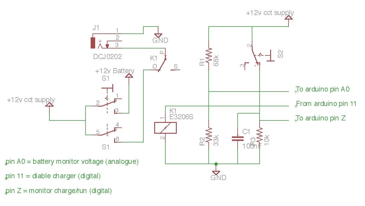
When the on/off switch is 'off' the charging input and arduino circuitry are completely disconnected from the battery. Off really is off. When this switch is 'on', the charge input is connected to the battery and the battery feeds the arduino circuitry which then monitors its voltage.
The second switch, only becomes active if the main switch is 'on'. When in the 'run' position, once the battery has charged to a sufficient level, the mower will start up as normal and go and mow some grass until the battery voltage drops below the lower threshold when it will stop and continue charging. When in the 'charge' postion, the mower will not turn on ts motors when the battery become charged but will continue to keep the battery topped up. If the battery reaches the upper threshold, the arduino will turn on the relay which will disconnect the charge circuit to prevent battery damage. The battery will gradually discharge through the relay coil until the terminal voltage drops to a safe level and then the relay will turn off and charging will resume. Therefore, when in the 'charge' position the mower will not fire up but click periodically as it regulates its battery voltage.
Battery Voltage Monitoring
As a rule of thumb, a fully charged battery will have a terminal voltage of 12.7 volts and this will drop to 12.4 volts when it has 75% of its charge left. To charge a lead-acid battery (and with the small solar panel, it will be a trickle charge), the charge voltage needs to be higher to get a current flow into the battery. For a current-limited source such as a solar panel, the panel's output voltage will be dragged down to that of the battery and rise slowly as the battery takes less charge. 14.4v is about as high as you should safely go and 13.8v is often used as the maximum charge voltage. The values I will use from this are shown in the table below. The battery voltage is fed through a 68k+33k potential divider and the equivalent binary value that the arduino will read can be found using:
(v * 33/(33 +68)) * 255/5
| Battery Voltage | Action | Arduino threshold |
|---|---|---|
| 12.4v | Stop mowing and charge | 207 |
| 12.7v | Start mowing and keep charging | 212 |
| 13.6v | Stop charging | 227 |
Construction
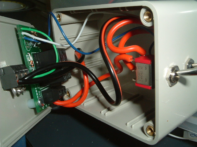
The switches and extra relay card were built into a small box that would be attached to the side of the cover and wires passed through an opening to the lid. This made the design more modular but I was concerned about the pickup issues I had seen earlier being a problem. The original distribution board was modified so the extra resistors needed to feed signals back to the ardiono were hosted there. I used my capacitor trick where possible to try and minimize interference on the measured inputs.
The box was drilled and the components mounted and wired up accordingly. I did not have an appropriate socket for the charge input so just brought the cables out through a hole for now. The box was attached temporarily to the lid with blue-tac and the wires brought inside to attach to the rest of the circuitry.
Testing
The locomotion code was disabled and the monitoring code enabled. After a few tweaks, the code worked as expected with the appropriate hysteresis functioning between the various battery voltage levels. The actual values retrieved from the ADC on which to perform comparisons were slightly different from those calculated, this being due to component tolerances.
The final stage involved enabling all the code to work together. The mower starts and moves off, then after a short delay the cutting blade motor is activated and at that point, the arduino seems to lose its marbles and stops responding to any form of input. This looks to be my old nemesis of power-line and/or radiation interference. I had added suppression capacitors to the new inputs but this time they do not appear to help. I suspect the power and signal cables entering the lid through one small opening may not be helping. Its back to the lab for more detailed testing. Once I solve this problem, the solar panel and googley eyes are all that remain.
Thoughts
Fixing the arduino problem
Things to try:
- Initially, leave wiring in place
- Disable charge/run circuitry
- Enable Charge/Run and disable monitoring circuitry
- Disable both
- Try a decoupling capacitor across the 33k resistor
- Failing all of the above, try re-routing wires
- maybe used screened wires.
Solar panel
The solar panel will rest on the hinged lid and give further respite from the rain although I need to be careful of run-off. It may be best to incline the panel slightly so that water runs off where expected.
The solar panel will add weight to the box lid so may affect opening/closing of the lid.
There is enough room to fit a 5 watt solar panel onto the mower. 10W would have been better but this would be too large for the mower footprint. In full sun, the specs of the 5W panel state that it can supply 290mA. I will make the assumption that usually we will get rather less than that, say 100mA. Also, being pessimistic, lets say there are only 8 hours of usable sunlight a day which would give 8 * 0.1 = 800mAH per day. Also assume the battery charging is very inefficient (50%) which would mean the battery would get 400mAH of charge a day. Our goal is 1.5Ah so this means if left abandoned on the lawn, the mower should take 1.5/0.4 = 4 days to recharge.
Using the above calculations, 4 days seems reasonable to me as this assumes bad light, poor efficiency and short days (i.e. the winter). The grass does not grow much in these conditions so will not need cutting much. One hot sunny day in the summer with long days would mean the mower would recharge in one day so would cut the lawn more regularly. So (on paper), this looks a reasonable charging solution, provided of course the mower isn't cowering under a bush somewhere and all the electronics have not been flooded in a torrential downpour!
If we go for a 2 hour run-time, these charge times will double.
Power Switch and Charger
I'd like to have two switches to control the power to the mower. The first would be a toggle on-off switch that completely isolates the battery and the charging input so the machine is well-and-truly off. The second would be a charge/run switch that would only work with the power switch in the on position. In the 'run' position, the battery would be connected to the charge input and when it reached a full charge value, the mower would automatically start up and mow until the battery fell below a lower threshold. In the 'charge' position, the battery would still be charged but when the battery was fully charged, the charge input would be disconnected, but the mower would not run. This would allow the mower to charge from a solar panel without starting up when no-one was around to keep an eye on it - something that would be wise initially at least.
A higher-level bump switch may be necessary in case the robot scoots under anything and hits the panel or cover without triggering the low-level bump sensors. I think the googley eyes will double up for this. They could be wired in parallel with the lower central bump switch which would cause the mower to reverse and turn around. This means no extra arduino pins would be required.
Battery Considerations
Lead Acid batteries are easy to charge and monitor. However, they are heavy and bulky. The terminal voltage drops considerably as they discharge and to get a long life from such a battery, it is best to not discharge it much below 75% of capacity. In this application, assuming we have a 1.5A current drain, this means we need a 7AH battery to get 1 hours mowing (assuming a 75% threshold). A two hour life would require a 14AH battery and this is getting on for 4kg in weight. This hive the driving motors more to move around so will cause more current drain and a higher possibility of stalling.
Another approach is to go for NiMh batteries. Wiring 11 or 12 of these in series would give 13.2 or 14.4V respectively and the discharge characteristic of NiMH cells mean that the terminal voltage will not drop appreciably during the discharge cycle. It is also possible to almost completely flatten them without needing to worry about keeping a safety threshold. AA cells are now exceeding 3AH rating so stringing 12 batteries together in series would give 14.4 at 3AH which would give a 2 hour run time at a fraction of the weight and space of a equivalent Lead acid battery. Less weight to cart around would mean less load on the driving motors.
Battery Monitoring
A potential divider will be used to bring the 12 volt battery voltage down to the 5V range for monitoring. An analogue input to the arduino will monitor this voltage.
The logic is simple, using 3 thresholds and some hysteresis. If the battery voltage falls below a preset minimum (75% of capacity), the motors are switched off and the charging input (solar) is connected to the battery. The mower will stay in this state until the battery becomes fully charged whereupon it will turn the motors back on and continue mowing. The charge input will still be enabled so the mower will receive some charge while mowing (although discharge >> charge). If the charge on the battery reaches a maximum threshold (that would damage the battery), the charge circuit it turned off completely until it falls within range of the two lower thresholds.
Note that this behaviour of waiting for full charge may mean the mower skulks around for a few days before starting but then it will have a full charge and an hour to run before becoming discharged again. If this hysteresis was not present, it would just wait until it charged slightly above minimum level, run for a few minutes and stop again. The battery would constantly hover around its minimum charge value and this will shorten its life drastically.
NiMH charging considerations
I've been rethinking battery charging. If we go for NiMH cells, it should be possible to charge them pretty quickly as the microcontroller can be pressed into service to monitor the charge process. If I can get charge times down to a few hours, then use of a solar panel becomes questionable. NiMH batteries need a constant current charge and to achieve this with a solar panel would mean using a much lower charge current.
Detecting the end-of the charge cycle is the main challenge with NiMH cells and this can be done with a fixed timer, delta-V, delta-T and even absolute terminal voltage. Some form of failsafe should also be included (from one of the above) as some detection methods can be unreliable with different manufacturer's batteries.
NiMH batteries need charging for C+50% to reach full charge, eg a 3AH battery would require 4.5AH of charge. Using 3A of charging current would therefore take 1.5 hours. Allowing for a safety margin (to prevent overcharging), 3 hours seems a good target so that charge current can be reduced as end-of-charge is reached.
5 mins at 1A charge.
1 hour 15 mins at 3 Amps - monitor deltaV + terminal
40 mins at 1 Amp - monitor deltaV + terminal
switch to trickle charge on termination or after 2 hours max.

0.6v/0.47R = 1.3 A charge
0.6v/0.33R = 1.8 A charge
Total = 3.1A

0.6v/12R = 50mA trickle charge

TIP122: b c e
BC548:  c b e

TIP122 Biasing:
(20 - 2.5)/10mA = 1.8k  // 2.5 is max. probably normally 1.2v vbe
Measuring delta-V: We need to measure terminal voltage every minute and store the result. Compare measured result with that of last measurement. if <= last, inc count. then replace old with new. Repeat for 5 minutes. If > last, do tot increment. If count >= 3, terminate.
	last = 0;
	cnt = 0;
	while (cnt < 3) {
		latest = measure();
		if (latest <= last) {
			last = latest;
			cnt++;
		}
		if (terminalVoltage >= 17.4) {
			cnt++;
		}
		if (elapsedTime > safetyTimeout) {
			cnt++;
	}
	terminate or switch to trickle.
terminal. If terminal voltage = 1.45*12 = 17.4 (say 17v), terminate.
If elapsed time >= 120 mins, terminate.
Battery Charging. If I could get a 1 hour run-time out of the batteries, the charge-time from a 5W solar panel is going to be prohibitively long. So my thoughts are now moving to using hi-capacity NiMH cells and having a fast recharge from the mains supply. There are few chargers available that will fast charge 12 AA batteries at once and although to build one would not be onerous, my thoughts strayed to power tools. Many power drills have 14.4v battery packs, and come with a fast charger suitable for NiMH or NiCd batteries. Adding a socket to such a charger would achieve exactly what I require, allowing for a full charge within 90 minutes. This also simplifies the lawnmowers charge circuitry, it reduces to a socket and a SPDT switch.
August 2012
| Home | Contents | Start | Prev | 1 | 2 | 3 | 4 | 5 | 6 | 7 | 8 | 9 | Next |