| Home | Contents | Start | Prev | 1 | 2 | 3 | 4 | Next |
Construction
Motors
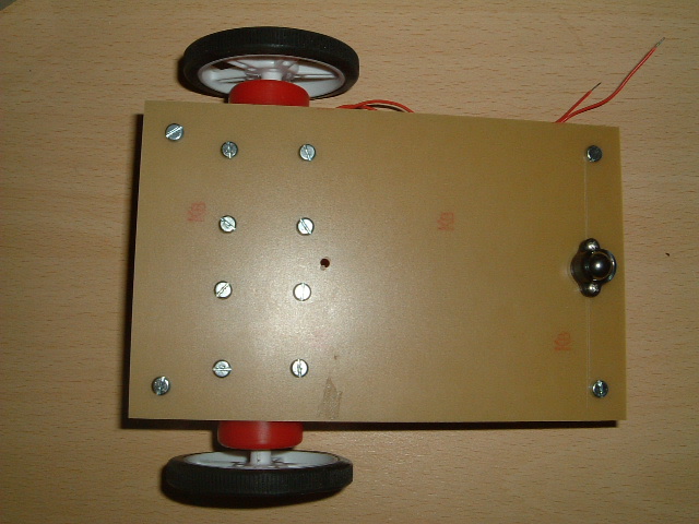
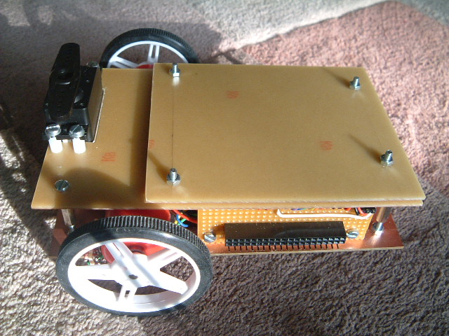
The motors and a roller were added first. The copper side of the board was mounted facing upwards as I was worried about possible reflections when line tracking that could cause errors. Originally, I was thinking about a four-wheel chassis with two drive motors connected via drive belts to the two free-wheels. This would give great stability and give tank-like steering. However, this hogs a lot of room and using a two-motor drive with a castor/roller would allow for more space for sensors. (compromise number one!).
Chassis Design
The lower chassis layer was where all the action is. Four pillars were mounted in each corner (using 3mm hardware) to allow the next layer in the sandwich to be added. The space between the boards was chosen to allow enough room for the motors and batteries to sit between the boards.

The Pluggable Interface
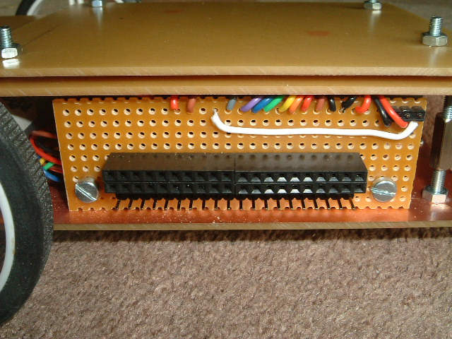
Next came the pluggable interface. I toyed with several types of connectors but needed a compromise between permanency and ease of reconfiguration. As this is a prototyping platform, any multi-pin plug/socket would limit versatility. The solution I chose in the end was to make a custom plug/socket using PCB headers mounted on veroboard, two rows of female sockets and one row of pins. The sockets can be used to interconnect via wires to the microcontroller - one pin at a time if necessary. The pins are mainly to attach test leads although a 20-pin plug could be added to bring all the data up from the lower board at once if necessary. I believe this gives a fairly flexible arrangement and with 20 pins, a lot of sensor data can be accommodated. The pluggable interface was brought out at the side of the chassis to give the maximum space on the lower deck and a short cable run up to the next deck.
Light Detection (LDRs)
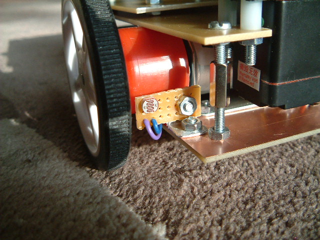
LDRs were mounted on small vero boards that were positioned at the front of the chassis, pointing forward. The connections were brought back to the connector.
Line Tracking
The line-tracker modules were added to the lower deck and wires brought up to the interface. I decided to bring not only theoutput from the sensors to the interface, but also the power supply. This is because a IR transmitter module can draw up to 30mA and there will be a lot of them on this robot. The option is therefore available to turn the sensors on and off, be it via a plug in the interface, or through software control.
![]()
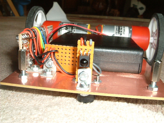
Batteries and wiring loom
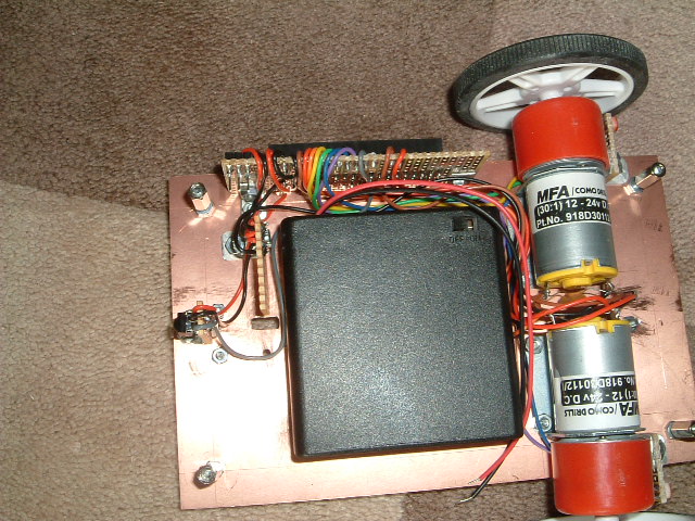
A battery compartment was added that contained 4 AA batteries. Although this is a clip-in box that allows for easy removal, I intend to add a socket so I can charge the batteries without the need to remove them. The wring from all the sensors was formed in a loom around the box to the interface board. Note there is an extra board mounted to the side of the battery box. This is used as a commoning-strip to allow the 5v and 0v feeds to be commoned where needed.
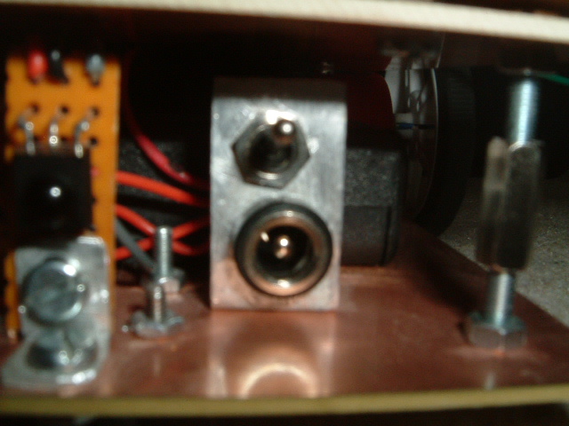
Charging and Power
The design is very modular and it is not onerous to remove the top-deck to change batteries but the time may come when there are lots of flying leads joining several decks together and dismantling the structure to change batteries may be inconvenient. I also needed to add a power on/off switch so it seemed sensible to combine the two. This uses a SPDT switch, that when 'on' will connect the battery to the robot and when off, will connect the battery to a power socket. The power socket can then be used to charge the batteries without being connected to the robot. The charging circuitry would be external to the robot (space limitations), but this is easily achieved by using a flying lead from a battery charger. The assembly was constructed on an aluminium bracket and mounted on the lower deck near the battery compartment. On day an autonomous charing station would be nice, but until that day is designed and built, a manual socket will do the job.
IR Receiver
An infra-red receiver was mounted centrally at the back of the robot. This was to allow some form of beacon to communicate with the machine. I have some plans for using a homing beacon to a recharging station that the robot could follow (in reverse) where it could then switch to line tracking to dock. It could also be used as a remote-control receiver to control the robot and put it into different modes. It's not on the immediate to-do list yet but it was wired up ready and the output brought out to the pluggable interface.
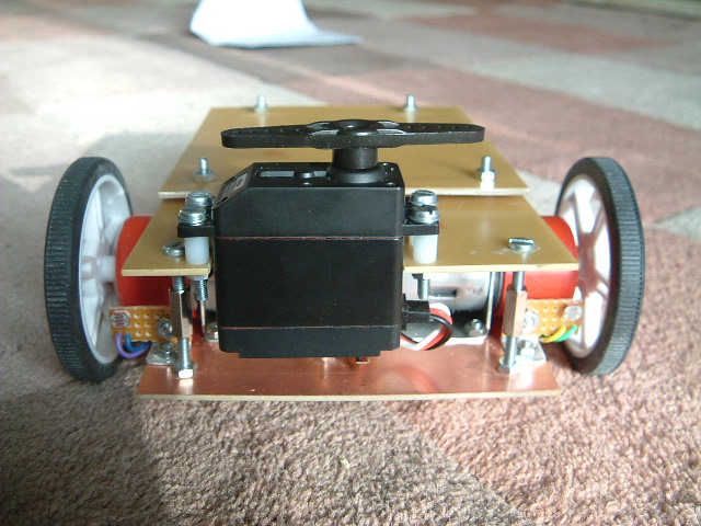
Servo Motor
Now came the servo motor. This needed to be mounted at the front of the robot, have a degree of rotational freedom and will be the main sensor used for navigation. This is the only actuator (so far) that is not mounted on the lower deck. It is physically mounted to the deck above although most of the servo actually sits in the space between the boards. I could have used a smaller micro-server as it has a small load (a ligh IR pinger) but I thought that a heftier servo gave options for other things (such as a servo mounting a servo).
Note the space under the servo. This is where I intend to add a short-range edge-detector IR pinger. To the right is a space where the PIR sensor will go.
Servo Connection
The servo connection was plugged into a socket mounted behind the interface board and the control signal brought out to the interface. This allows the upper deck to be removed easily. I may put the socket on the upper board later if more sensors are used there, but for now all the sensors/actuators are brought out to the same interface connector.
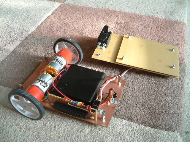
Microcontroller Mounting
Rather than mounting the microcontroller directly on the upper deck, I thought it would be more flexible to use a standard 'controller board' that could could be mounted above the deck on its own card. This would allow me to replace the controller board without turning the upper deck into swiss cheese with various mounting holes. So the bare board is shown below. I will make a few copies of this now so I have correctly sized and drilled boards suitable for various microcontrollers.
Note in this picture that there is space behind the servo to allow it to turn. Also, there is room above each wheel to add wheel encoder hardware which is an area I may wish to experiment with later.
Today, I finished the construction of the robotic hardware and am now ready to move onto putting a brain on the chassis and make it do something.
| Home | Contents | Start | Prev | 1 | 2 | 3 | 4 | Next |