| Home | Contents | Start | Prev | 1 | 2 | 3 | 4 | Next |
Microcontroller Selection
Having used the PIC16F690 on several projects, it looked to have many of the features needed for a small micropcontroller brain. However, I found a small microcontroller board (RKP18Motor) with a L273D H-Bridge on the same board but it required the use of an 18 pin PIC. This board was intended for use with a PIC AXE (Basic + bootloader) but I was sure I could modify it for my purpose.
I decided to use a PIC16F88 device as this had most of the functionality of the PIC16F690, but in an 18 pin package. This device has less I/O pins than the PIC16F690 and less Analogue inputs. It does support nanowatt technology although I am not sure if this will be of any use in this application.
I have a PICKIT2 programmer so needed to modify the board to support ICSP and then set about running some test programs. It will make programming far easier to use C rather than assembler so I downloaded the HI-TEC C compiler for use with the MPLAB IDE. So this board was to be the brain of the robot. After modifying the board to use a header suitable for the PICKIT2, the board was mounted on a daughter-board that could be mounted on the upper deck of the chassis. A couple of header blocks we mounted adjacent to the board so that connections could be brought off the board for easy interconnection.
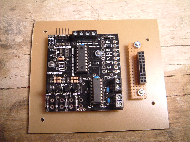
Microcontroller Board
The microcontroller board uses bits RB4-RB7 to drive the H-Bridge which is permanantly enabled. The 4 LSB of PORTB feed driver transistors. This suits well as PORTB can be used for output and PORTA for input. There are 7 multiplexed analogue inputs and PORTA contains 5 of these so that looks a reasonable use of resources. The PIC16F88 contains one hardware PWM so insufficient for motor speed control but it my prove useful for controlling the servo. The output is on PORTB.
Driving the Motors
The RKP microcontroller board contains an L293D H-Bridge. Motor direction can be accomplished by setting the inputs to the H-Bridge, two bits per motor. I wrote a simple motor-control library that controlled these bits (on PORTB) and wrapped them in higher level robotMovement API. The API does not allow for motor speed control but is sufficient for directional control.
Robot Movement API
void robotStop();
void robotForward();
void robotReverse();
void robotRightArc(unsigned char amount);
void robotLeftArc(unsigned char amount);
void robotRightSpin(unsigned char amount);
void robotLeftSpin(unsigned char amount);
A simple test program (motortest.c) was written to move the robot forward, backward, turn and spin in both directions. This was mainly to give some form of calibration and to see the underlying hardware was working as expected.
... and it works! As suspected, the 12 volt motors are rather underpowered, especially after going through the H-Bridge. The RKP board has a polarity protection diode in 5v line. I replaced this with a wire link to scavange some more volts and it is enough to allow the robot to maneuver gently around on a hard surface. On a table, it trundles around slowly with little noise but it will stall on a carpet. For testing this is fine, but I am concerned that if left to stall, the current consumption could destroy the H-Bridge. I decided to replace the motors with lower voltage equivalents. To keep the slow speed (as the low voltage motors will be operating at maximum speed, but 12V ones were not), the new motors have a 100:1 gear ratio rather than 30:1.
The new motors arrived today, 1.5-3v models although ok up to 6V. I did some testing using 3v and they move the robot about easily on carpet with lots of torque.They run a bit faster and more noisly than the previous motors but not overly so. The supply protection diode was replaced on the controller board so that the supply was brought down to 4.4v. The H-Bridge drops about 1.5v, so the motors will be powered at 2.9v - perfect.
Servo Control
Now the locomotion was understood, attention was turned to driving the servo. For this application, we are really only interested in looking left, looking right and looking straight ahead although the ability to turn to any position may be useful in the future. So the servo api should reduce simply to:
	void servo_move(unsigned char how_much);
	void servo_left();
	void servo_centre();
	void servo_right();
The last three functions would be nearly wrappers on servo_move(). The servo I received had no driver documentaion and a few searches on google revealed servo control to be a bit of a vague area. However it boils down broadly to:
- Supply 5v and 0v to the servo
- Send a PWM stream to the control input to move to the desired position
- The PWM stream has a 20ms period
- The pulse width ranges between 1ms to 2ms
Rather vague, and each servo type may vary slightly but overall it seems the period should be at least 20ms, but accurracy is not that important. 1.5ms seems to be the pulse width or 'centre' and 1ms and 2ms give -45 degress and +45 degrees respectively. Some servos have a greater range of movement so the PWM period can move outside the 1ms and 2ms limits, provided the servo physical endstops are not encountered.
The PIC16F88 has a hardware PWM which I thought would be useful for servo control. This uses TMR2 which (as yet) has not been assigned to anything else. However, running with a 4MHz clock, the longest period that can be set in 4ms, even when using the 16:1 prescaler. This is too fast for the servo so I looked to other means of generating the PWM stream.
It would be possible to generate the PWM stream with a purely software solution using delay loops. However, while in a busy-wait loop, the processor can do nothing else and 20ms is a long time to wait. As a compromise, TMR0 was used to generate the 20ms period and software used to create the pulse width which would mean a maximum of 2ms delay.
The servo control API was written using the interrupt service routine and a test program used to wrap it. I'm unsure at this stage how to decouple the API from the ISR so that the servoControl can move into its own library.
Well, the control of the servo worked as expected. For my servo, I found 1.65ms was centre and I could range from 0.9ms to 2.1ms when running some tests. I have hit a problem in the servo gets drivem fully counter-clockwise (hitting the end-stops) on startup or reboot. After many hours of head-scratching, this turned out to be a byte value overflowing on startup that manifested itself as a PWM burst with a very short pulse width. Now that is fixed, all looks to work fine.
Sensor Inputs
Basic locomotion and servo control was understood and implemented. Now was the time to start looking at some of the sensors and reading their values into the microcontroller. This will then allow programs to be written so that the robot csn interact with its environment.
IR Range-Finder
The most important sensor to master was the IR range finder. This should be relatively easy to interface with as it produces an analogue output voltage proportional to the strength of the reflection it receives. This will be the first sensor I will tackle as this, combined with the servo and locomotion APIs will give me enough functionality to build a robot that autonomously finds its way around a room. That is my first goal and once that is achieved, I will see about adding the extra sensors as needed.
Ideally, it would be useful to pass the sensor values and robot state back to a computer (or LCD screen) to monitor what is going on. However, I will get the basics working and then work on reporting and telemetry although testing the IR sensor may prove difficult wiythout it.
| Home | Contents | Start | Prev | 1 | 2 | 3 | 4 | Next |