| Home | Contents | Start | Prev | 1 | 2 | 3 | 4 | Next |
Software
It had been decided at the outset to program the microcontroller in C rather than assembler. I feel to have 'done-my-time' with assembler and useful as it was to learn the hardware architecture, C allows the problem to be realized at the application level rather than at the register level. It is a long time since I programmed in C and it takes a while to mentally adjust from an OO language back to a hardware control language.
As each area is tested, the plan is to develop APIs which can be used later in more complex applications. I was originally going to package these as libraries but the HI-TEC C compiler will compile and link multiple C-source files without a problem which is more than suitable for my needs. After all, I just need a way of controlling complexity but am not intending to be a library writer! It may cause a little code-bloat but we will cross that bridge if we need to.
Initial tests seem fine, even using callback functions called from the interrupt service routine. With the movement and servo code split off into APIs and common headers, I'm starting to get enough building blocks to make something useful.
Analogue Sensor API
Many of the sensors used by the robot produce an output voltage that is proportional to the value being measured (be it IR-reflection, light etc). In order to read these analogue values, the PIC can be configured to enable the ADC, select the apropriate input and run an ADC conversion. The PIC16F88 can multiplex up to 7 analogue inputs although with the hardware board I am using, only 5 are really usable.
All ADC reads require a acquistion and settle time setup and each read will be similar except for the pin it reads. It therefore seems sensible to create an adc_read() API that can be used for all analogue sensors. i.e.
adc_read(unsigned char which)
It would then be possible to create simple wrapper functions for specific sensors. eg:
adc_read_ir()
adc_read_ldr_left()
adc_read_ldr_right()
The ADC can be setup as 10 bit, 8 bit and left or right justified. This can be done during PIC initialization or even using an API method although this may not be really worth the effort as we are getting close to the hardware here:
adc_setup(boolean left_justified, boolean ten_bits)
However, these are all niceities and I will flesh this out as we go. For now, I just want to get something working!
Testing and Integration
Reading the IR Pinger
The IR pinger was connected and a simple adc test program written where RA0 was used to read the the analogue output from the sensor. The digital output was sent to PORTB which fed an LED bar graph. Moving a hand back and forth in front of the sensor resulted in the bar graph beciming increasingly more illuminated the closer my hand got to the sensor. Incidentally, the maximum output was obtained when the reflection distance was about 2cm. Any closer than this and the sensor goes 'blind'. Objects could be detected up to 30-40cm away. This does show that if something is really close to the sensor, it will not see it so some kind of bump sensor will be necessary for this blind-spot
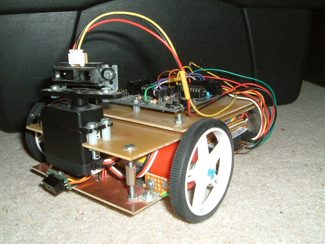
The IR Sensor was now mounted on the servo and the output leads modified so that could be plugged into rest of the development platform. Taking stock, we now have APIs to control movement and direction, turn the servo and read from the IR sensor mounted on the servo. Test programs had be written for each module in isolation, then movement and servo, so it was now time to wire all three together.
Hardware Matters
Up until this point, much of the hardware has been abstracted but now that several modules are to be used together, it is necessary to screw down particular pins for certain operations. Although an infinitely configurable system in nice in theory, dedicating certain pins simplifies the application software and allows for simple function calls to perform certain operations.
| Function | Type | Port | PIC pin | Board I/O |
|---|---|---|---|---|
| IR Pinger (eyes) | input | RA0 | 17 | ip0 |
| Right Motor | output | RB4, RB5 | 10, 11 | MB port |
| Right Left | output | RB6, RB7 | 12, 13 | MA port |
| Servo | output | RB0 | 6 | R6 (op0) |
This means that the adc_read_ir() function will always sample the analogue voltage on RA0. I can see going forward, that if a new microcontroller chip is used, new versions of the software will be required due to different pin configurations. There still seems lots of legs in the picf88, but if I upgrade to another processor later, I will make it a very large one and will probably stick with it for a while.
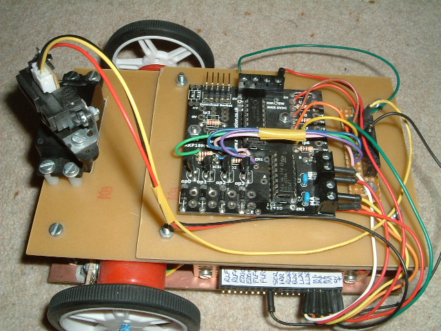
It was time to hardwire into the microcontroller I/O board. The relevant pins were wired to the adjacent connector board to allow them to be pluggable. For analogue inputs, it does mean the associated resistor may vary depending on the sensor. Initially, 4 of the 5 inputs were brought out to the microcontroller connector each having a 1k pulldown resistor. There is room for 4 outputs and a few of spare slots for power and ground. The output port (Port B) from the PIC was wired straight to the connector, leaving the driver transistors dangling. This meant teeing-off the board where necessary, direct from the microcontroller and left the driver transistors available for other usees. These will be connected as and when needed (for example up to LEDs, relay boards). However, for the initial goal, we only need one output (RB0) which is used to drive the servo. Since the main function of the robot will be to maneuver (4 bits) and move the servo (1 bit), the remaining Port B outputs (RB1-RB3) could be utilized as inputs if necessary although I beileve they may be better utilized turning power on and off to the various sensors via the driver transistors.
Sandy's ports.

RA0 = IR (head) input
MOTOR = RB4 - RB7 (RB4,RB5=RightMotor, RB6,RB7=LeftMotor)
RB0 = SERVO
| Home | Contents | Start | Prev | 1 | 2 | 3 | 4 | Next |