| Home | Contents | Start | Prev | 1 | 2 | 3 | 4 | 5 | 6 | 7 | 8 | 9 | 10 | 11 | 12 | 13 | 14 | Next |
Perimeter Detection
This mower will be have collision sensors so it can get around unforeseen obstacles. An additional sensor will be detecting a perimeter wire around the garden. I believe this can be achieved by using a small Radio Frequency Transmitter and essentially using the perimeter wire as an aerial. It only need a near field range of about 10cm so it will not need to be a powerful transmitter. I assume the receiver will use a coil/tuned circuit to detect the electromagnetic field emanating from the perimeter wire, amplify the signal and use it to signify the wire is nearby.
I need to ensure the signal will not cause electromagnetic interference and choose a frequency that is easy to work with. My initial thoughts were to use the superhet IF frequency of 455kHz as there are lots of tuned amplifiers available for this frequency. However, broadcasting on this frequency is pretty antisocial and probably illegal as well. Choosing a low frequency will mean I have less issues with RF pickup, miller capacitance and all the usual headaches involved with high frequencies. I'm wondering if I can get away with super-audio, somewhere in the range 50kHz to 100kHz. A standard amplifier circuit may be good enough to use in the receiver although I could use a tuned circuit load to give better selectivity. A few experiments are called for...
RF Detector Ideas
The resonant frequency of an LC circuit is given by:
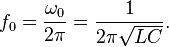
As I needed to start somewhere, I used a 1mH coil and a 10nF capacitor to give a resonant frequency of about 50kHz. I think this may be a bit on the low side but it gives a good place to start.
The Detector circuit is a fairly standard two stage amplifier that is fed from the output of the tuned circuit (50KHz). At resonance, the amplifier will have a gain in the order of 500. The output of the amplifier is fed into diode clamp (level shifter) and rectifier with the aim of producing a DC output when the inductor detects the presence of a 50kHz signal. The diodes used are schottky devices as these have a lower Vf, in the order of 200mV rather than 600mV for their silicon counterparts. The output of the rectifier is fed through Q3, a driver transistor that will be used as an input to the microcontroller.
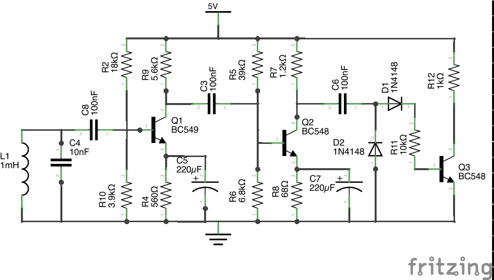 Schematic 1: RF Detection Circuit
Once the circuit was constructed, the resonant frequency was measured as 50.2kHz
| Home | Contents | Start | Prev | 1 | 2 | 3 | 4 | 5 | 6 | 7 | 8 | 9 | 10 | 11 | 12 | 13 | 14 | Next |