| Home | Contents | Start | Prev | 1 | 2 | 3 | 4 | 5 | 6 | 7 | 8 | 9 | 10 | 11 | 12 | 13 | 14 | Next |
Interconnections
Most of the components are ready now, with the exception of the multiplexer and RF Transmitter. However, some more permanent connections are required to pull the machine together. All the electronics have been constructed in stand-alone and shielded enclosures with terminal posts to make them modular enough for testing. I have thought long and hard about ways of wiring things together and decided initially that all sensors wires will come back to the arduino in one multi-way screened cable.
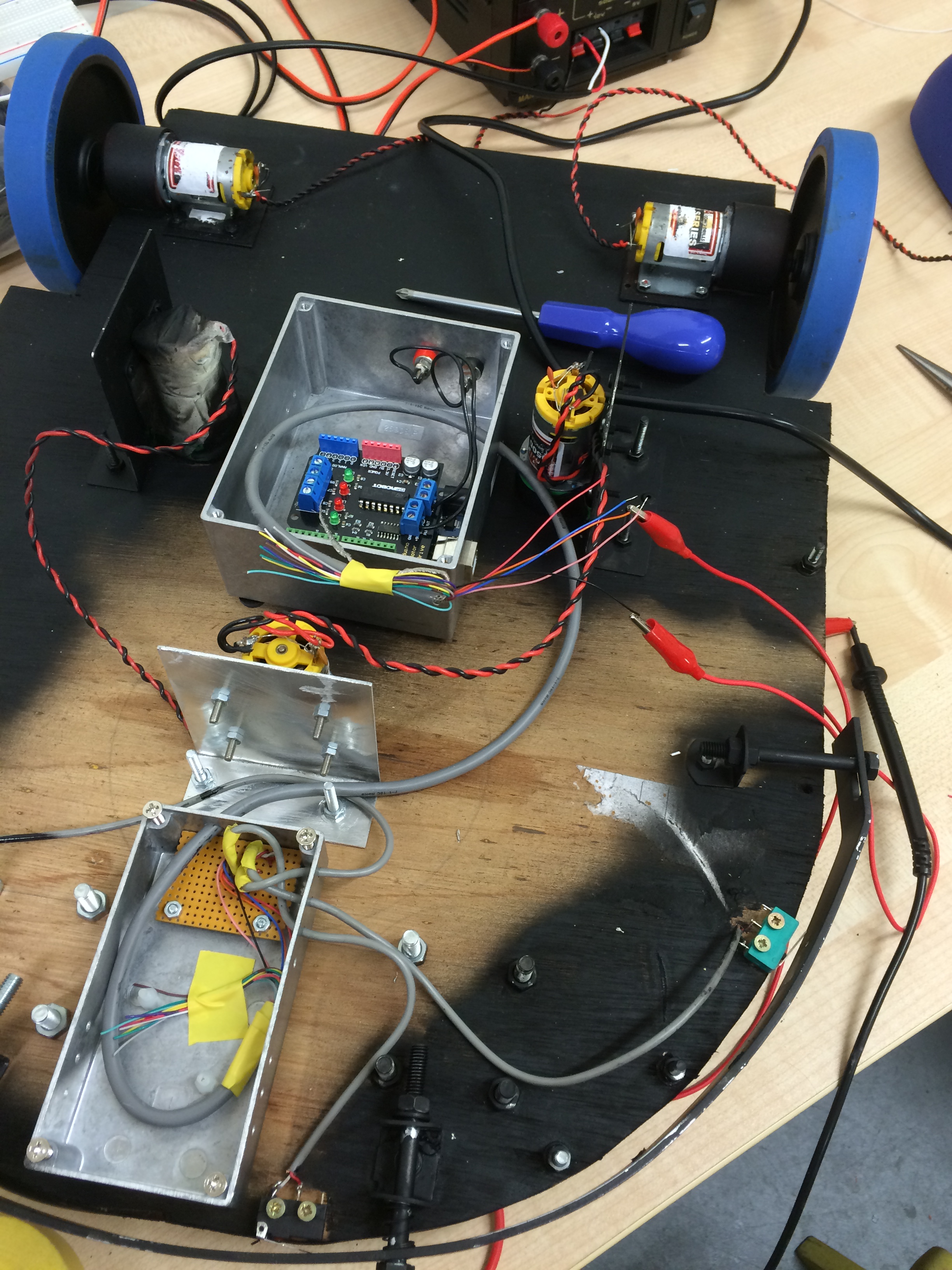
After deciding to get the mower ready in two phases, namely collision sensors only initially, this is a picture of wiring progress now the RF Detector and Mux chip have been removed. Note that during testing, I found one of the microswitches to be faulty and had to replace it (the green one!).
Arduino Connections
| pin | i/o | type | endpoint | colour | route | reason |
|---|---|---|---|---|---|---|
| GND | out | GND | MUX | black | via main loom | |
| +5v | out | Power | MUX | red | via main loom | |
| 4 | out | digital | Motor2 Direction Control | Reserved for use with Motor driver | Via connector to motor driver shield | To control the direction Motor2 rotates |
| 5 | out | PWM | Motor2 Speed Control | Reserved for use with Motor driver | Via connector to motor driver shield | To control the speed Motor2 rotates |
| 6 | out | PWM | Motor1 Speed Control | Reserved for use with Motor driver | Via connector to motor driver shield | To control the speed Motor1 rotates |
| 7 | out | digital | Motor1 Direction | Reserved for use with Motor driver | Via connector to motor driver shield | To control the direction Motor1 rotates |
| 9 | in | digital | LH Bump Switch | pink | main loom to mux, then onto switch | For LH collisions |
| 10 | out | digital | Cutter Relay Enclosure | purple | direct to the relay enclosure | To turn on the cutting blades |
| 11 | in | digital | CE Bump Switch | orange | main loom to mux, then onto switch | For head-on collisions |
| 12 | in | digital | RH Bump Switch | blue | main loom to mux, then onto switch | For RH collisions |
| Home | Contents | Start | Prev | 1 | 2 | 3 | 4 | 5 | 6 | 7 | 8 | 9 | 10 | 11 | 12 | 13 | 14 | Next |