| Home | Contents | Start | Prev | 1 | 2 | 3 | 4 | 5 | 6 | 7 | 8 | 9 | 10 | 11 | 12 | 13 | 14 | Next |
Construction
Chassis and Blades
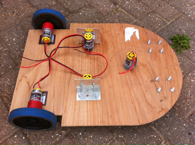
The chassis was made from 6mm marine ply according to the floor-plan. The rear wheels are recessed so that they do not protrude from the edge. Holes for the motors were drilled and these were secured using custom aluminium brackets and 4mm bolts. To get a snug fit onto the board, I found in necessary to remove the plastic gearbox shrouds from the motors. I may look into creating custom gearbox shrouds as it helps keep detritus out of the cogs.
The front of the machine was rounded off with a jigsaw and the castors mounted using 6mm bolts. This what the top of the platform looked like during construction.
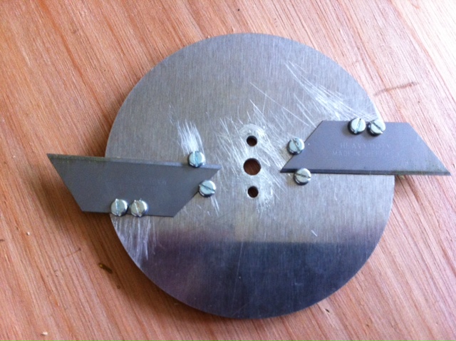
After the encouraging results from the test blade on the cutting jig, I set about making a working blade rotor. I made these on some 100mm aluminium disks (3mm thick). Each blade protrudes 20mm from the edge which gives a 140mm cutting area. Three such blades were made which when mounted, give a cutting width of the desired 30cm easily. The first blade produced looked like this:
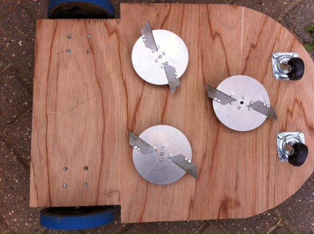
The blades were mounted to the 6mm gearbox shafts using aluminium couplings in the triangular pattern set out on the floor-plan so the view from the bottom of the machine looked like this:
Perimeter Detector Construction
This was built on veroboard which was pretty straightforward. I learned from Lawna that a lawnmower is an electrically noisy environment. Having a sensitive RF amplifier in the design is probably going to confound the situation. My plans this time are to mount the electronics in a screened (and earthed) box to minimize these issues. I hope to run a wire 'ariel' around the front of the mower to increase the detection area. This could cause me problems with pickup, I'm not sure as yet. Hopefully, keeping the tuned circuit in the screened box and running an ariel to it is better than having the tuned circuit outside the screen. Tests will show the best setup and I expect this part of the project will be quite time consuming.
Feeding a 5v p/p 50kHz signal down a wire was detected by the circuit at about 1 cm away. Increasing the output of the signal generator (up towards 10v p/p) was picked up at 3cm. This is using the tuned circuit as the detector. Using a small wire aerial 20cm long increase sensitivity to over 20cm range. In short, the circuit seems to work as designed and I intend to adjust sensitivity by varying the output of the transmitter rather than varying the gain of the receiver.
The next stage is to put the whole circuit in a screened box with a small wire aerial (to be fed around the front of the mower) and see how we fare with a long transmitter cable outside the lab.
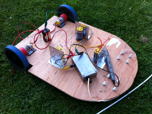
While testing I found I needed to connect the metal box to earth (-ve) otherwise I started to see oscillations. It may be worth adding a capacitor from the output (collector of Q3 to ground)to ensure spurious RF does not cause interference and thus give rise to false triggering. This may add some damping to how quickly the circuit triggers but there is a little hysteresis in there already. Here is the first static testing on the lawn. A signal generator was pushing an 8V p/p 50kHz signal through 10 meters of cable and I found it could reliably be detected at a distance of 4cm.
RF Receiver Aerial
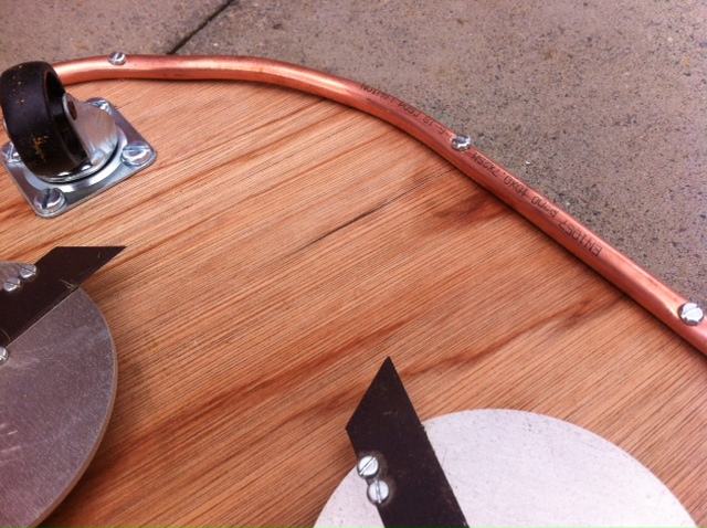
The RF receiver used by the perimeter detector ideally should have an aerial that wraps around the front of the mower so it can detect the perimeter when approaching it from any direction. Being at the front of the machine means it is in the firing line for any collisions so it needs to fairly robust. After thinking about this for some time, I decided to use a copper pipe bent around the front of the machine and mounted underneath the chassis as this will give the best reception pattern. This arrangement does leave an overhanging lip which may cause problems when reversing out from a collision so it may be necessary to mount the pipe on the top of the chassis, or apply some curved moulding to cover it. However, it seems a good starting point.
Here is a picture of the pipe mounted on the underside of the mower. It is 10mm copper pipe and is quite substantial. Note that the pipe extends along one side for a distance. This was done in case there is a need to follow the boundary wire which may be useful in the future for finding a charging station. The plan is to connect the ariel input to one end of the copper pipe although it may be worth experimenting by connecting to the centre.
| Home | Contents | Start | Prev | 1 | 2 | 3 | 4 | 5 | 6 | 7 | 8 | 9 | 10 | 11 | 12 | 13 | 14 | Next |