| Home | Contents | Start | Prev | 1 | 2 | 3 | 4 | 5 | 6 | 7 | 8 | 9 | 10 | 11 | 12 | 13 | 14 | Next |
Graveyard Information
Perimeter Detection Ideas
Circuit 1: A single stage Amplifier
A single stage classA amplifier with a voltage gain of 10 and an input impedance of at least 100k was lashed up, the input being driven by a parallel LC circuit as in schematic 1
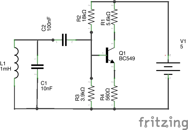 Schematic 1: Single Stage Amplification
A signal generator output (10v p/p) was fed down a wire and the wire brought near the coil in the circuit and the frequency adjusted for resonance (Q1 collector). The circuit picked up the transmitted frequency but only when within 1cm and the output was very small (10mV). The Q factor of the circuit was not that responsive, being a slow drop-off either side of 50kHz, somewhere in the region of 20kHz bandwidth. This was not unexpected as the circuit only has a low gain, but it is a good place to start.
The 5.6k load was then swapped out for an identical LC load tuned to 50kHz. The response was much better, being able to pickup the oscillations up to 4cm away and when close to the wire (<1cm), the response was much larger (100mv+). The Q factor was much higher, the circuit was very peaky with a bandwidth of 4kHz. The active load was changing the gain of the circuit, making it very much higher and with two tuned circuits, the Q factor was also being sharpened.
Circuit 2: Two stage Amplification
The next stage was to have a second amplifier in cascade. This has a higher output current and has a voltage gain of 17. If combined with the original circuit, we would be aiming at a theoretical gain of 10 * 17 = 170.
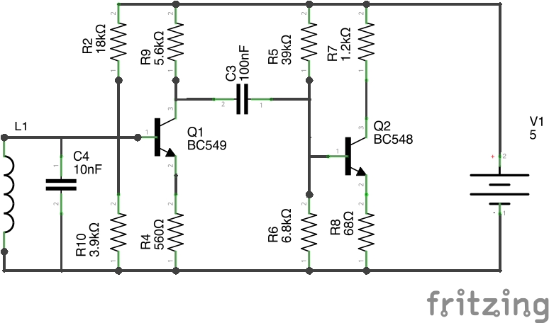 Schematic 2: Two Stage Amplification
TODO Results
Resonance: Distance from transmission Wire, output Voltage (Q2 collector) adjacent, 500mV 1cm,200mV 5cm, 100mV 10cm, 50mV 1Khz away from Resonance: adjacent, 100mV 1cm, 50mV 5cm, 20mVNow the 5.6k load resistor was again swapped out for a second tuned circuit. Therefore the overall gain will become much higher, and then be multiplied by 17, again with a very peaky response.
TODO Results
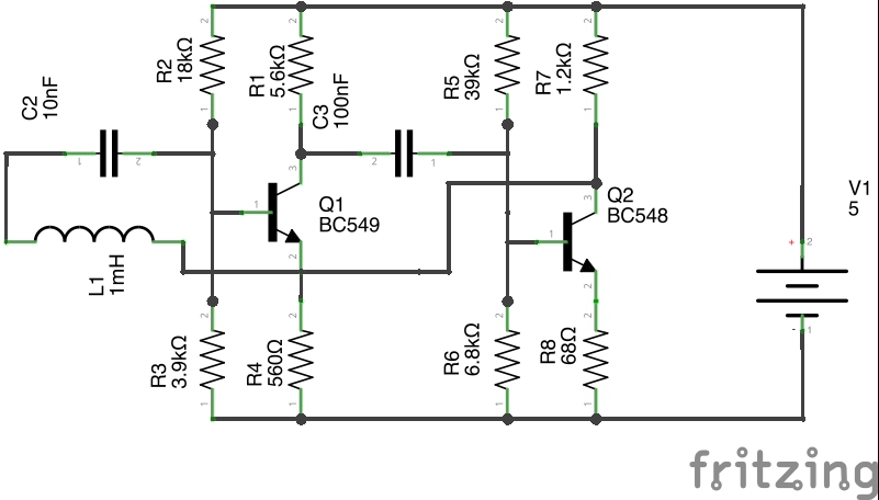
Resonance: Distance from transmission Wire, output Voltage (Q2 collector) adjacent, 1V 1cm,250mV 5cm, 100mV 10cm, 100mV 50cm, 50mV 1Khz away from Resonance: adjacent, 50mVThe two stage amplifier gave very encouraging results although I believe an extra stage of amplification is required in order to bring the level up to a suitable voltage for envelope detection. I think an amplifier with an adjustable gain of between 1 and 10 would do the job nicely. Three transistors is not excessive but it may be more advantageous to use a darlington instead. I have some of these handy so it may be possible to use a high gain darlington tuned amplifier followed by a single adjustable gain transistor. Of course, I could use an op-amp as a 50kHz signal should be within its bandwidth.
Circuit 3: Two stage Amplification with Tuned Regenerative Feedback
This circuit is a simple two stage amplifier but this time the output of the second stage is fed back via a series tuned circuit to the first stage. The circuit will have a gain of 10 * 170 for all frequencies other than the resonant frequency, which will mean positive feedback will ensue. I suspect this circuit may oscillate and will need some damping resistance to be added.
 Schematic 3: Regenerative Feedback
TODO Results
This created an oscillator.Circuit 4: Tuned Amplifier with Regenerative Feedback
This circuit used a tuned load on the first stage and passes the output to the second stage. The first stage gain will become much larger at resonance. This is amplified by the second stage and the output then fed back to the input to amplify it further. Again, I expect this to oscillate as we will have a lot of gain and the circuit will need to provide some form of resistive damping.
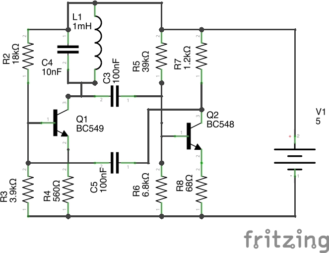 Schematic 4: Tuned Amplifier with Regenerative Feedback
This created an oscillator
Colpitts Oscillator
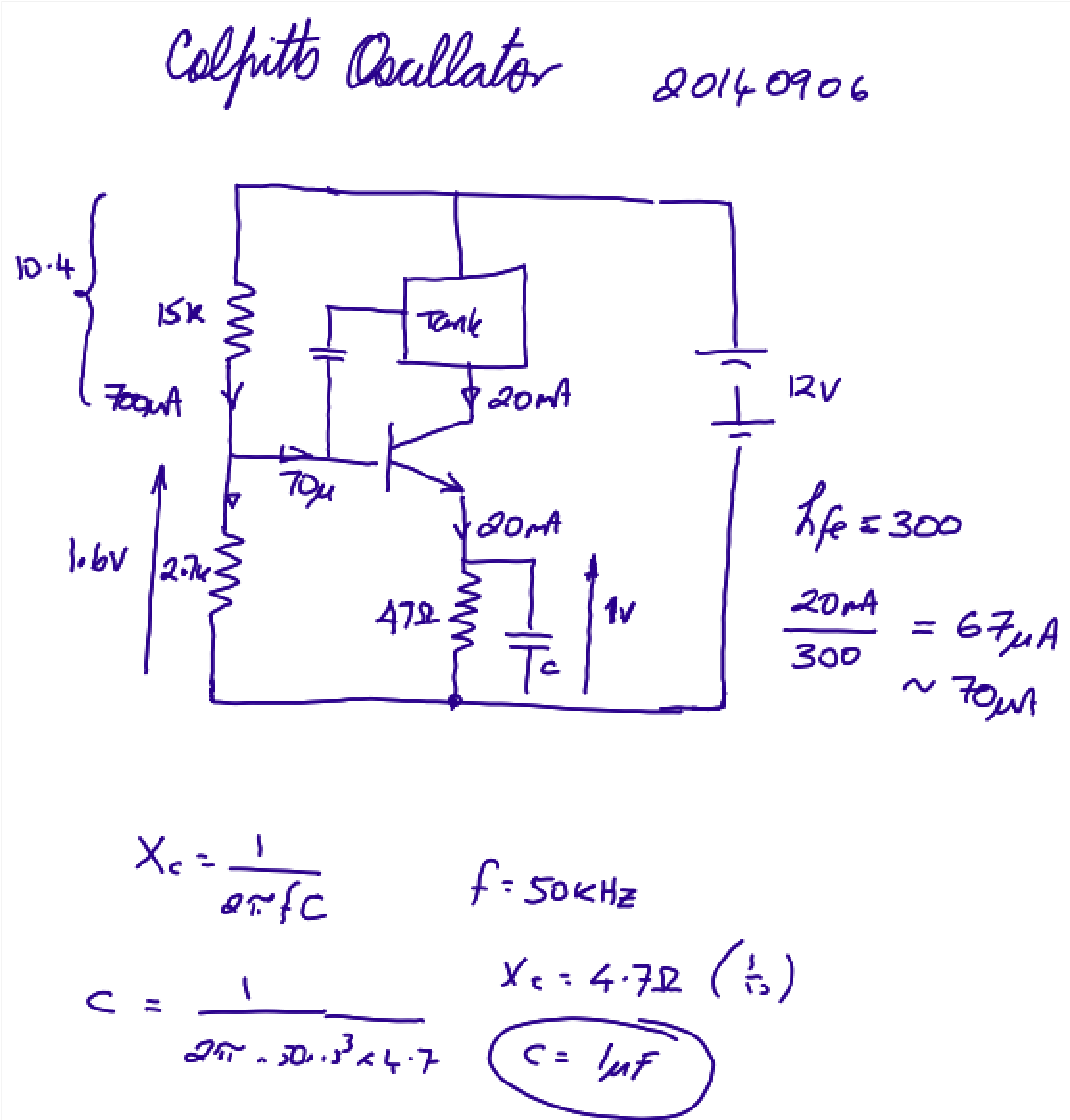 Colpitts Biasing Design
Perimeter Detection Tests
Using the copper pipe aerial made the rf detector into a 50kHz oscillator! This manifests itself as constant boundary detection. Reducing the aerial size (with a wire) and normality was restored. Either we need to reduce the rf amplifier gain or find a different aerial. The problem with reducing amplifier gain is that valid detection may not occur. Here is a detection test using a shorter aerial.
Options
- Leave copper pipe in situ and run an extra wire around the front of the mower. It may need to be shorter.
- Run a wire inside the copper pipe. Could even earth the pipe. This may reduce sensitivity and/or detection range but it could stop false triggering. Maybe the pipe acts as a shield normally and then as a concentrator when we approach the perimeter. If that was so, that would be very fortunate!
- Cut the pipe into 3 or 4 sections, each being a smaller aerial. This could reduce false triggering and make each aerial more directional. We could possibly use an analogue switch/ multiplexer to know which aerial is sensing at any one instant.
To move forward, I will initially use a shorter wire aerial although will start to investigate using an analogue multiplexer such as the 4052 or 4051 devices.
To use the multiplexer option, we need two extra digital outputs to drive the multiplexer.
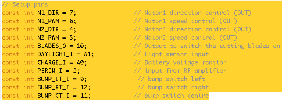
    Pins available are:
    8 - ok
    3 - useful for interrupts
    13 - has an led connected on arduino. Still an output so should be ok. Check pull-up ?
Ideas
TODOs
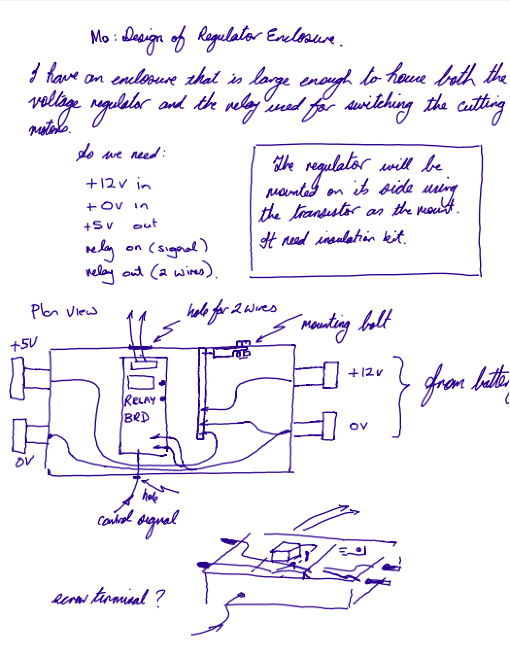
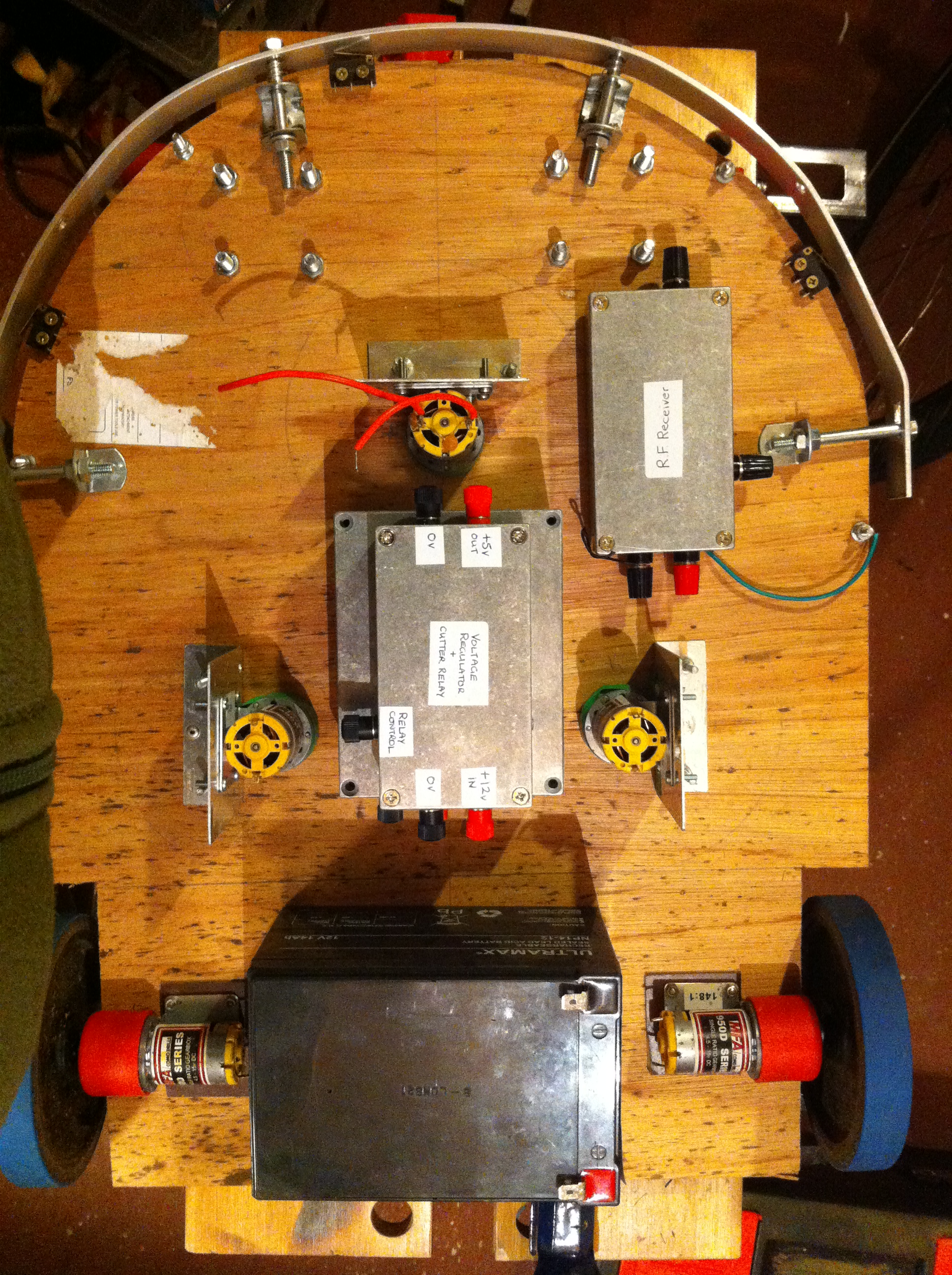
4. we need to consider mounting components. This will cover
- the rf detector
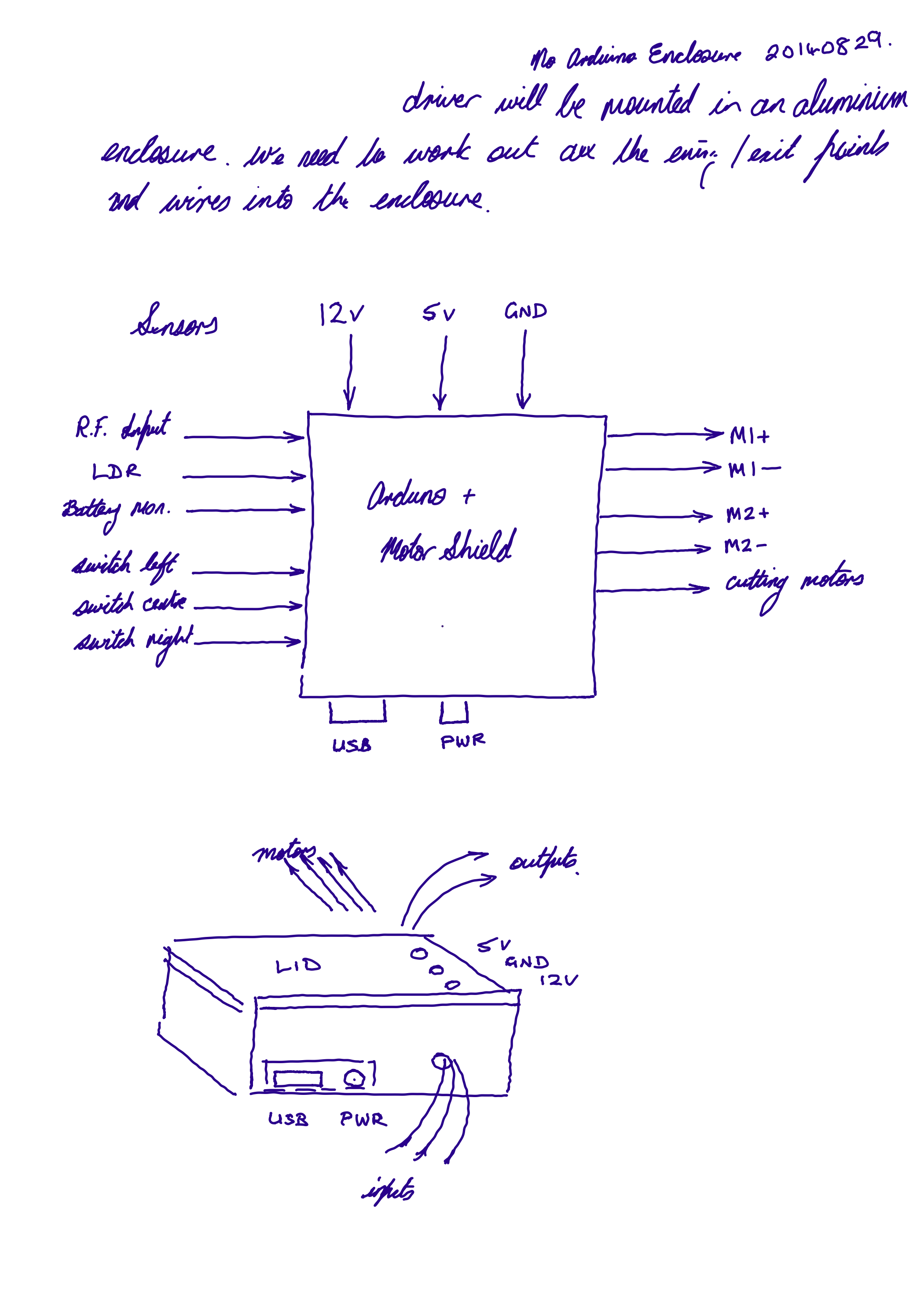
- the main arduino + motor driver
- a voltage regulator (+5v)
- a 50kHz transmitter. This could be a square wave generator although
I might give a Colpits oscillator a punt.
5. We need a central earth point
6. All connections need screened wire.
7. Possibly we need ferrites.
8. The microswitches need mounting.
9. Arial connection to rf detector
10. When we need to make the transmitter!
Earthing and RF Pickup
I had many headaches with Lawna due to the noisy environment in which the lawnmower operates. All the parts worked individually, but the arduino suffered RF pickup when everything was working together. I aim to take steps to head these issues off from the start which will include:
- Placing the electronics in screened boxes.
- Connecting sensors/components with screened cables.
- Use a single earthing point to minimize earth-loops.
- Use ferrite beads on cables where necessary.
Weatherproofing
The electronic components and motors/batteries need to be enclosed in a simple form of cover. Options available are:
- Use a plywood cover.
- Make a metal cover from sheet metal.
- Make a card cover and coat it in fibreglass resin.
A metal cover made from thin aluminium may be the easiest option although I will need to master aluminium brazing to achieve it. Otherwise the resin solution may be a better option as I am familiar with it from my Wind Turbine days.
Locomotion
The current locomotion motors work well but need to be throttled back to provide more effective mowing as the speed over ground is too fast. This is similar to my findings with Lawna (where the motors were salvaged from). It may be that when the motors are throttled that the mower struggles to move the heavy lead-acid battery around. If this is the case, I have found a source of motors that have more gearing so I could run them at a higher speed and get a slower overall speed. Just something to keep in mind.
I need to consider the option of not using a direct-drive for the motors but instead use an external gear-chain or belt/chain drive. This should give much better connection to the wheels. I'll do this only if necessary.
A third option is to reduce the diameter of the wheels. Smaller wheels could be a simple solution that solves a few problems here:
- The blades get lower to the grass and give a closer cut.
- The mower will move more slowly over the ground.
- Less torque is required to turn the wheels. This in turn may enable PWM speed to be reduced further.
Handwritten Original Design Notes
We need to augment this now. We require two extra output pins which we will use to control the aerial multiplexer. Pins available are: 8 - ok 3 - useful for interrupts 13 - has an led connected on arduino. Still an output so should be ok. Check pull-up ?
Controlling the Mux
int readPerimeter() {
  int val = 0;

  for (int i = 0; i < 2; i++) {
    switch(i) {
      case(0):
      digitalWrite(MUX_S0_O, LOW);
      digitalWrite(MUX_S1_O, LOW);
      val = val + digitalRead(PERIM_I) * 1;
      break;

      case(1):
      digitalWrite(MUX_S0_O, HIGH);
      digitalWrite(MUX_S1_O, LOW);
      val = val + digitalRead(PERIM_I) * 2;
      break;

      case(2):
      digitalWrite(MUX_S0_O, LOW);
      digitalWrite(MUX_S1_O, HIGH);
      val = val + digitalRead(PERIM_I) * 4;
      break;
    }
  }
  return val;
}

val values:
1 = left bump
2 = centre bump
4 = right bump

Anything else is a combination which we can treat as a centre bump for now.
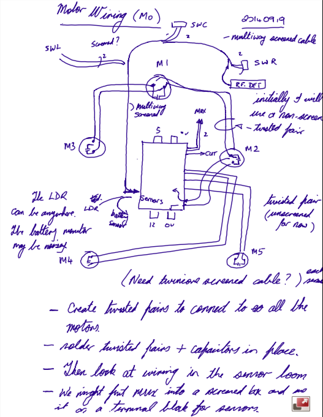
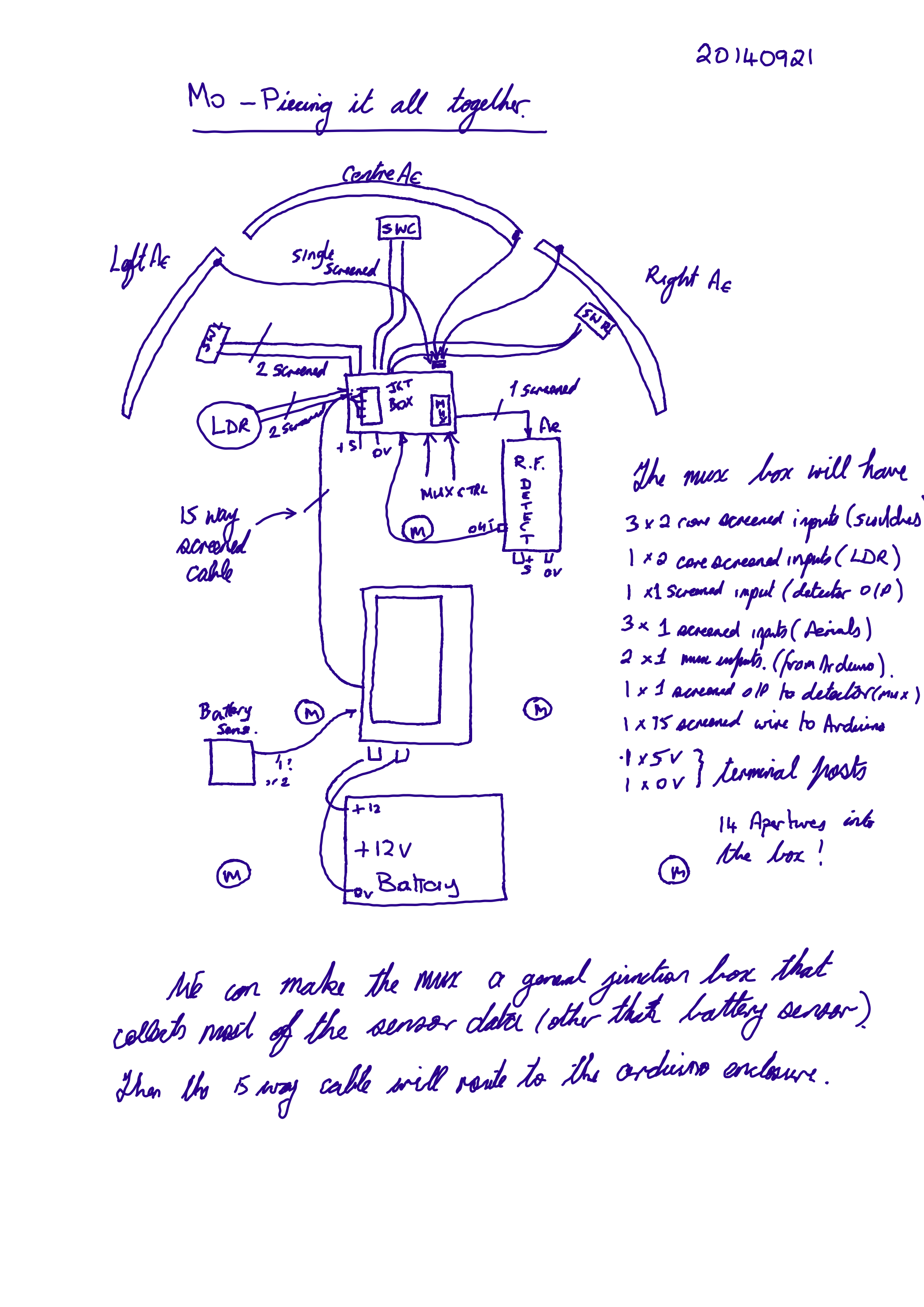
Wiring
- switches 6 wires
- LDR 2 wires
- Battery voltage 1 wire
- RF detector 1 wire
10 input wires. I have chosen a 15 way cable to give some room for expansion.
It may be better to make everything active-low switched. The bump sensors are currently active-high.
There are a few control outputs from the Arduino:
- Enable Cutting motors 1 wire
- Multiplexer 2 wires
- Locomotion control (4 wires)
7 output wires
Power Cables
The power cables to the motors should be decoupled and screened. At the bare minimum they should be twisted pairs.
- 3 wires come from the aerials and into the mux.
- 1 output from the mux to the RFD.
- 1 output from RFD to Mux then onto junction then out to arduino.
- 2 wires from arduino into junction, onto mux (select)
- 2 * 3 from switches to junction then 3 out to arduino.
- 2 (1) wires from LDR to junction onto arduino.
- Earth and +5 from arduinio
| Home | Contents | Start | Prev | 1 | 2 | 3 | 4 | 5 | 6 | 7 | 8 | 9 | 10 | 11 | 12 | 13 | 14 | Next |