| Home | Contents | Start | Prev | 1 | 2 | 3 | 4 | 5 | 6 | 7 | 8 | 9 | 10 | 11 | 12 | 13 | 14 | Next |
Field Tests Phase 1
Mowing Performance
All three blades were enabled and the mower programmed to mow in a rotating square pattern. The Speed was set to 250, near maximum. Mowing performance is good. Although it might be rather fast, the area gets covered very quickly and with three blades running, the grass seems to be mowed well. The cut is a little high, but I will keep it like that until everything else is finalized.
Bumper Tests
Phase 1 field tests were performed to see how Mo performs using just the bump sensors. This was first undertaken just with the locomotion motors running and then again with the cutter motors running. I was delighted to see that there was no interference when the cutters were running. This was one of the main problems I had with Lawna so the time taken to mount everything in a screened enclosure was worth it.
Results were really encouraging and the grass was mowed well, and in good time. There were three areas that need addressing:
- The bump sensor is a little high and can miss low-lying obstacles. I was aware of this during the build and will need to to add a skirt to the bumper to allow it to detect lower objects. This may increase resistance when pushing through grass but the bump sensors are the last line of defence so need to be as reliable as possible.
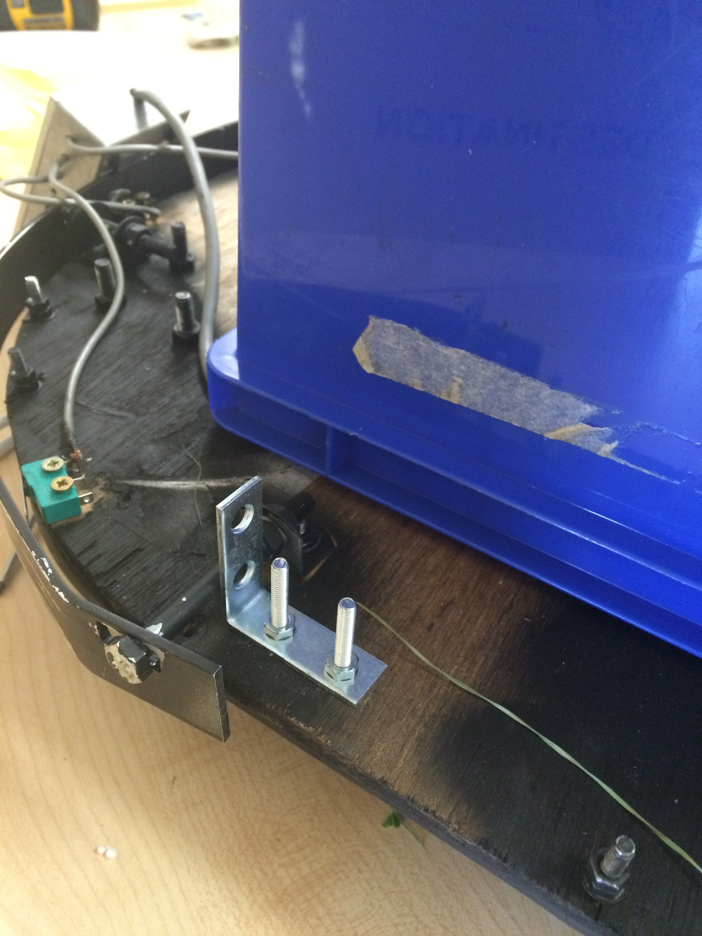
- The bolts at either end of the bumper pass through a bracket that is mounted to the base with one bolt. If these bolts strike something, they can twist on the mount which can cause a microswitch to stay pressed which cause the mower to keep taking evasive action and reversing. Some kind of reinforcing bracket can help here.
- The bolts at either end of the bumper are fixed so if these strike an obstacle, the sensor is not activated. I can overcome this by mounting a dome over the bolt-heads that sits on the bumper and does not touch the bolt. Something like a half tennis ball may work here.
Here is the bracket used to fix the twisting of the bolts. You can also see the plastic enclosure which we will be using to keep the grass out!
Perimeter Detection Tests
This will probably move to graveyard shortly
The perimeter detector works well and can detect the wire at 10cm or so. Initial tests were using just one single ariel. It detects fine although in this configuration, cannot tell which side of the robot has moved over the perimeter wire.
Perimeter Detector Improvements
It would be great if the perimeter detector could be directional so a more informed decision could be made when it was detected. It may also be possible to hug the perimeter wire to get back to a charging station at some stage in the future. Ideally, being able to detect the wire straight ahead, to the left or to the right would be useful as it could use the same avoidance code that will be used by the microswitches (although not necessarily so).
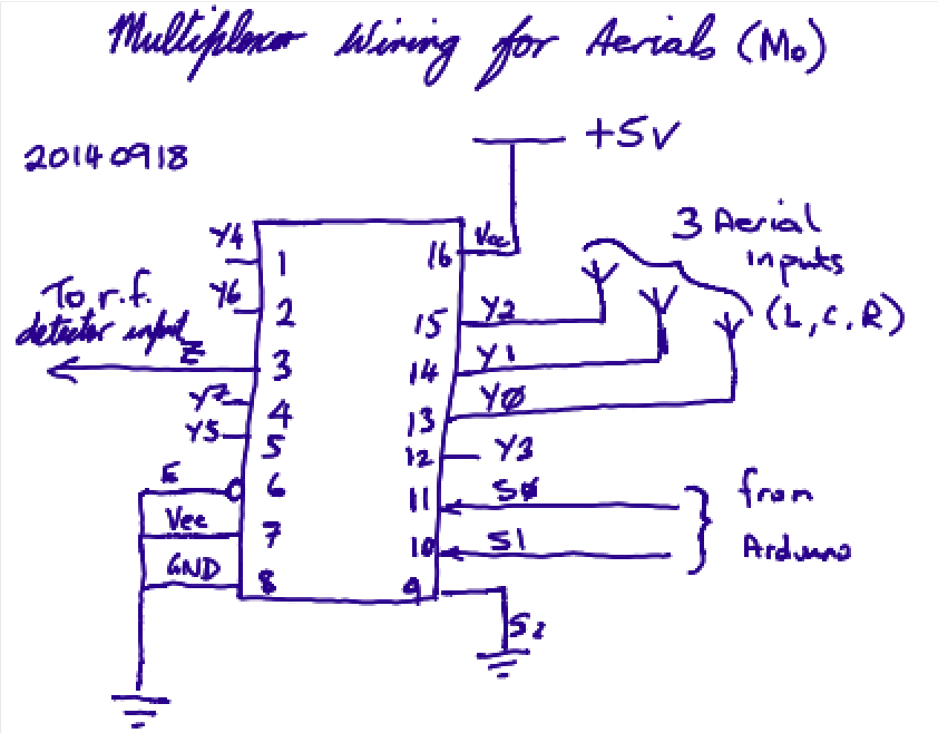
To achieve this directionality, the copper antenna-pipe was cut into 3 sections, each being a smaller antenna. The signal from each antenna was fed into an analogue multiplexer whose output was fed into the RF Detector. The software was altered so that when reading the perimeter detector, it cycles through each antenna and will therefore know which of the three has detected a signal. Sometimes more than one antenna may pick up a signal so we can cater for a few different states.
An 8-way 4051 multiplexer was used although I am only using 3 of the 8 inputs. If it works well, it may be possible to increase the number of antenna segments. To drive the multiplexer, we need two extra outputs from the arduino and these are pin 8 and pin 13. Pin 3 is still available but I want to keep this available as it is one of only two interrupt pins.
The following is a quick sketch of how the multiplexer will be wired in this implementation. Unused inputs will be tied to ground.
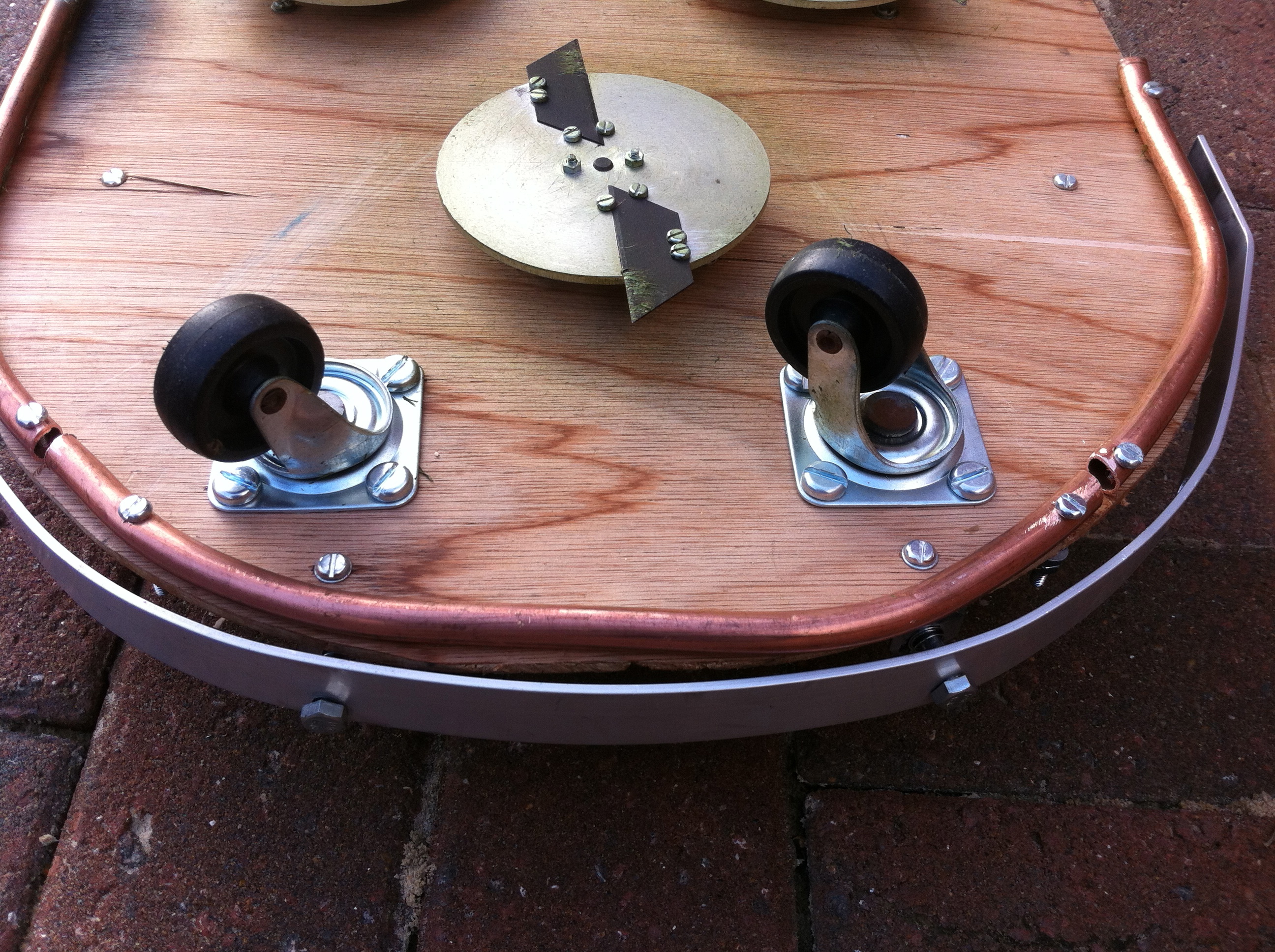
The copper aerial has been subdivided into 3 sections ready for the multiplexer
Weatherproof Enclosure
I need some kind of enclosure to protect the battery and electronics. Now it is being used in anger, there is a lot of grass and dross flying about. Ideally, I would like to minimize the ingress of this into the electronics (although the screened cases will help a lot here. I decided to move all the electronic enclosures into the space between the cutting motors and cover them and the battery with a plastic recycling box, suitably modified for the purpose. I may come up with something better later but this is a perfectly adequate cover although I need to work out how to paint it. (I've had problems with painting plastic previously and it is one of the things the girls enjoy doing best.
Mo Personality
Mo will need to look the part and needs personality for the kids to really feel they are involved. I'm thinking onf bulging eyes at the front. I can have an emergency stop switch as the nose. Under that we need a moustache (of course!). As the bumper needs extending, this could be made to resemble teeth.
| Home | Contents | Start | Prev | 1 | 2 | 3 | 4 | 5 | 6 | 7 | 8 | 9 | 10 | 11 | 12 | 13 | 14 | Next |