| Home | Contents | Start | Prev | 1 | 2 | 3 | 4 | 5 | 6 | 7 | 8 | 9 | Next |
12 Watt wind turbine stator construction
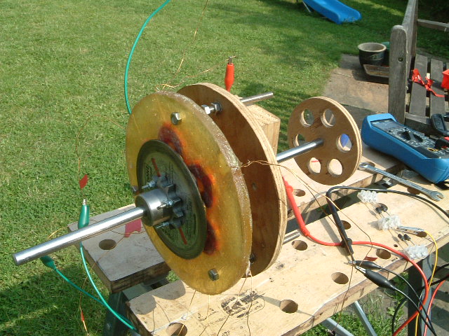
I taped six coils onto the test harness as shown below, added a rotor and monitored what I produced in practice.
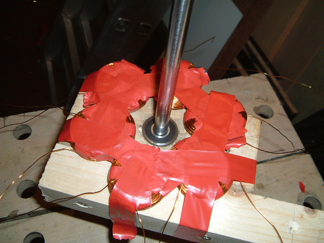
The test harness is shown below. Nothing too high tech going on here! Notice there are more than one magnet on the rotor. This was to test that each magnet added actually increased the output voltage from the coils.
Well, all looked ok so it was time to make the stator a more permanent affair. As mentioned earlier, twice the output can be obtained by having the coils sandwiched between two rotors so to enable this the coils are set in fibreglass resin. The first job is to make a stator mold. This is done by cutting a circular hole the size of the required stator from plywood and bolt/screw it between two further pieces of plywood. It is best to make the whole thing easy to dismantle as the stator may get stuck in the mold after casting so make it easy on yourself to remove it. The plywood disk cut out from the mold will come in handy later.
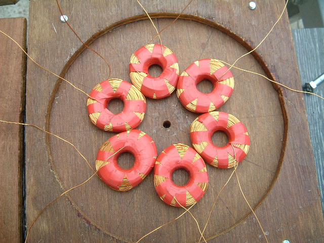
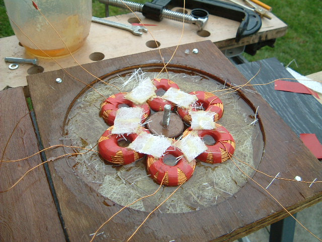
The base of the mold should be marked out appropriately so you know where the coils are going to sit to ensure they line up with the magnets. The picture below shows how the coils are temperarilly added to the mold to enable them to be lined up correctly with the markings on the mold base. Note that all the coils are added the same way up and I marked their ends with tape so I knew which end was which. This makes wiring the coils together when the mold if finished a lot easier.
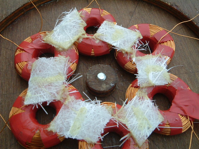
A small plywood disk is put in the centre of the mold to allow it to fit around the rotating shaft without rubbing. In fact, making it larger allows for more alignment tweaks and uses less resin. Once the coils were in position some fibreglass matting 'bridges' were placed between them and saturated with superglue. It doesn't do any harm to put glue over the coils either, but the whole lot must not be glued to the mold! The snot-coloured gloops are a different glue I had to use when I ran out of superglue. When it has dried, the coils should be a solid unit (the fibreglass matting goes hard withe the superglue) and can be carefully removed as a whole unit.
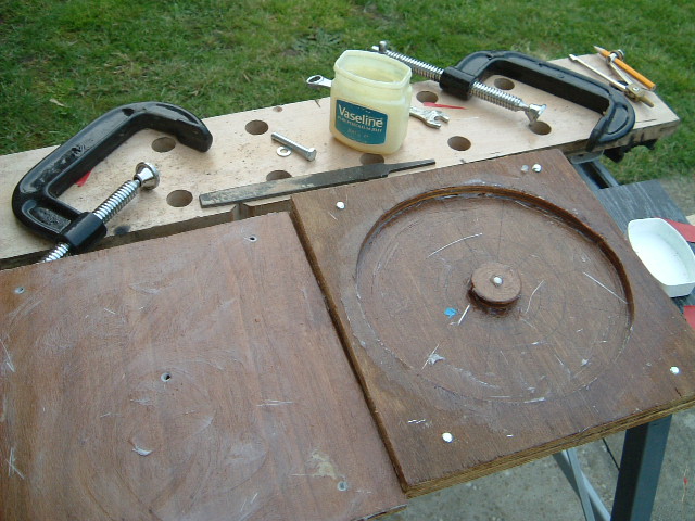
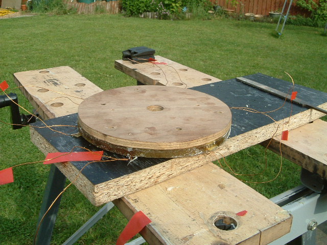
The coils were removed from the mold, and the mold was greased with vasiline as shown below.
Note that all the individual coil ends are being brought out to the edge. I suppose this makes things potentially less reliable but it gives the freedom to change the stator wiring from single-phase to three phase star or delta as a later date if necessary. I learned my lesson from the previous attempt which had the connections hard-wired in the resin.
Another fibreglass mat ring was added on top of the coils and more resin added until it was fully wetted and the mold was full. Now the top was bolted on and some G-clamps added to ensure all was a flat as possible and it was left to set.
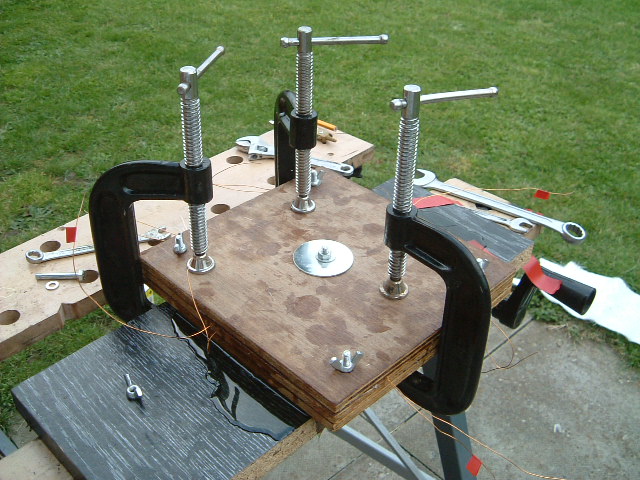
It is necessary to make sure the mold is tightened securely so that the resulting stator is as flat as possible and of a known thickness (I used 12mm thick plywood). When the resin had set, the stator was removed from the mold and any small holes (due to bubbles in the resin) touched up with glue. In retrospect, it would probably have been a good idea to tap the mold with a hammer to try and chase out any bubbles.
Now the stator needed drilling and mounting. I decided to use the large disk of plywood that had been cut from the mold for this purpose as it was exactly the same size as the stator. Two holes were made in the wood to mount it to the box section. Next, thre 6mm holes were made through the stator and plywood disk near the edge of the stator (greater than the radius of the rotor). Care was taken to ensure these holes only went through resin and not copper wire
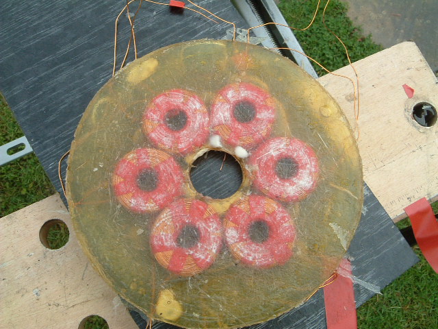
Before going any further, the stator was mounted on the test-jig (using the same plywood stator mount) to see that the stator was producing the type of output predicted. The picture below shows stator and rotor mounted on the test harness. Each coil output was measured and for one rotor, the output was 800-900 mv @ 220rpm, more or less spot on.
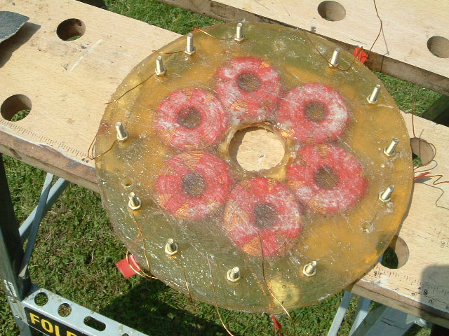
All the ends from the coils were still protruding from the stator disk so these were tidied up by attaching them to 4mm brass bolts drilled through the stator near each coil. The enamel is best removed from wire by burning it on a gas cooker and then cleaning it up with emery paper. The completed stator shown below is finally ready for mounting.Brass bolts were used for two reasons:
- Brass makes for good electrical connections and is corrosion resistant.
- The bolts must not be magnetic as the magnets will be attracted to them as the rotor rotates.
10-Jul-2007
| Home | Contents | Start | Prev | 1 | 2 | 3 | 4 | 5 | 6 | 7 | 8 | 9 | Next |