| Home | Contents | Start | Prev | 1 | 2 | 3 | 4 | 5 | 6 | 7 | 8 | 9 | Next |
12 Watt wind turbine alternator assembly
Assembly
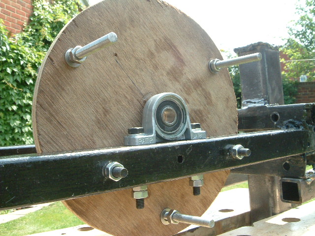
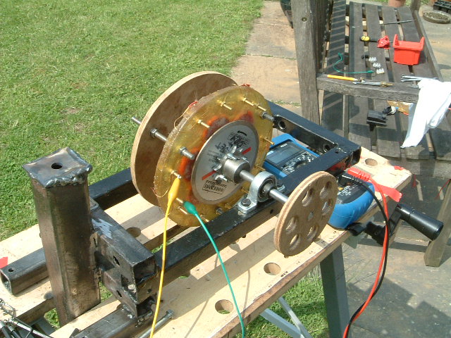
First the bearings are mounted on the frame. These are bolted down tightly and locking nuts used to make sure they stay there. Next the stator support is bolted to the back of the machine. The figure below shows this. Note the three long pieces of all-thread (100mm each) that pass through the mounting. These will eventually pass through the equivalent holes in the stator to suspend it between the two rotors.
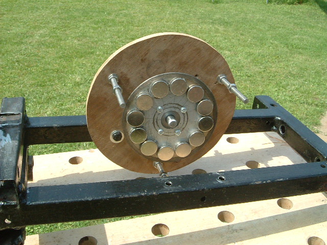
The shaft was threaded through from the back of the machine, through the first bearing and stator mount and then the first rotor was added. The grub screw was not tightened yet.
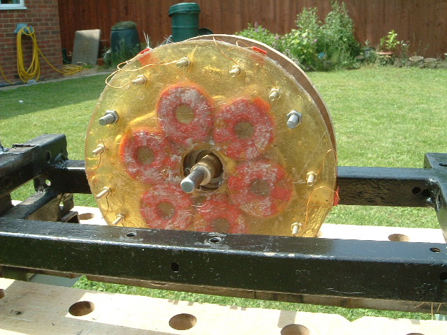
The stator was then mounted to the three sections of allthread that had been mounted through the plywood stator mount. These bolts and nuts must be made of A4 grade stainless steel otherwise the magnets from the rotors will be strongly attracted to them and 'cog' as they pass by. Brass would probably be ok although it is a bit soft, but that would be expensive way to mount a stator! A quick note on stainless steel. Generally, it is available in two grades, A2 and A4 depending on the composition. A4 grade is more expensive and more corrosion resistant (and often used in marine environments). A2 stainless steel is magnetic and A4 is not, so we need A4 stainless hardware to mount the stator.
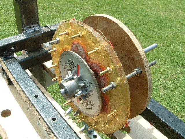
When the second rotor is mounted, the two rotors will attract each other and try to slide together along the shaft, sandwiching the stator between them. Rather than let the rotor grub screws/glue take this strain, it is easier to mount a spacer on the shaft that is just long enough to ensure the rotors are the right distance appart. This wasdone with a drilled dowel that is a tight fit on the shaft so it rotates with it (and the rotors). This can be seen on the shaft in the diagram.
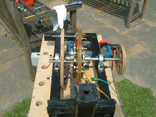
The second rotor was then pushed onto the shaft. The magnetic attraction from the other rotor pulled it toward the stator so the stator was only loosely mounted at this stage. The rotor will self-align and although the rotors should be identical, it is best to make sure they are always aligned the same way if dismantling as this gives more consistent results both electrically and mechanically (ie for balancing purposes).
The second bearing was mounted and the shaft pushed through it to finish off the alternator. The stator bolts were adjusted so that the stator sat evenly between the rotors and the rotors could turn freely without rubbing. This gave a clearance of abou 1.5mm either side. The stator bolt were then tightened up. The bolts on the fibreglass should be tight but not overtightened as this could crack the resin. The rotors were then locked down with the grub screws.
A side view of the completed alternator is shown below
The completed alternator was then electrically tested. Below you can see the output from one coil - 1.7v @ about 200rpm. The coils were then all connected in series using insulated wire between the brass bolts. The final output was measured and was around 11 volts @ 220 rpm.
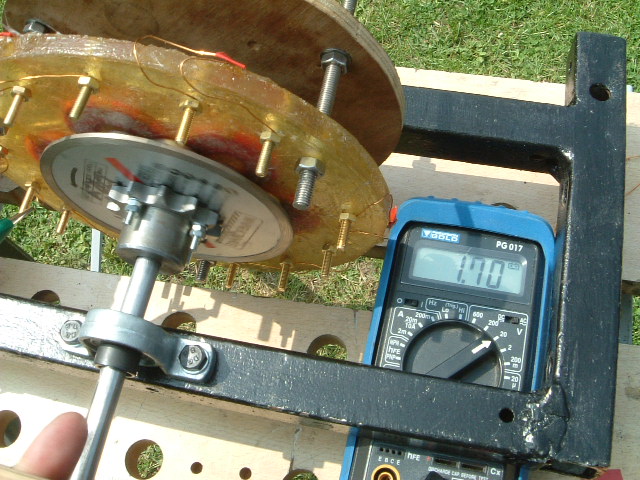
The voltage generated by the alternator is AC volts at the frequency of rotation. When measured with an AC voltmeter, the reading is volts RMS. When this is fed through a full wave rectifier with a suitable smoothing capacitor, the DC output will be given approximately by:
Vdc = Vac * 1.414 - 1.4v
Where 1.414 is the square root of 2 and the 1.4 volts is two diode drops in the bridge rectifier. Given an ac output of 10.8v ac, this gives us:
10.8 * 1.414 - 1.4 = 13.9 Vdc which is just about right for charging a car battery.
Once happy with the setting of the alternator, it is a good idea to lock the bearnings and sprokets onto the shaft using a suitable glue. Locktite bearing glue is fantastic stuff but once it is on, its a pig to get off again so I would only reccommend this when you are sure you do not need to dismantle things again. In my case, I will need to dismantle the alternator to paint and weatherproof parts of it so at this stage it has not been glued. The 10mm bearings need gluing as they have no other mechanism to hold them to the shaft (I used some temporary collets during testing as seen onthe diagrams) but the final alternator will require the bearings to be glued to the shaft. By the way, if you think gluing a gear to a shaft will not provide a suitably strong attachment, think again!
10-Jul-2007
| Home | Contents | Start | Prev | 1 | 2 | 3 | 4 | 5 | 6 | 7 | 8 | 9 | Next |