| Home | Contents | Start | Prev | 1 | 2 | 3 | 4 | 5 | 6 | 7 | 8 | 9 | Next |
DC Voltage Regulation
Regulation
Now came the task of handling the regulation of the turbine output voltage as I have seen in excess of 30V being generated on a windy day. With a battery that requires charging, this is not an issue as it draws the current it needs and pulls the generated voltage down to the required level. In effect, it acts as an active load, performing the regulation necessary.
The problem arises when the battery is fully charged. Then it will not draw much current and so will not drag the output voltage of the turbine down to a reasonable level. The voltage applied to the battery terminals will then start to rise and this will eventually damage the battery. What is needed, is a mechanism that will allow maximum current through to the battery when it needs it, and then prevent the voltage being applied to it rising above a threshold value (about 14.4 volts maximum).
Regulator Design Considerations
The regulation can be achieved by using either a series or shunt controller. A series controller drops voltage and limits current being passed to the load by effectively acting as an active resistor in the power-path. A shunt controller will simply short the generator output to ground, pulling down the output voltage and diverting current to ground. The shunt mechanism is much more appealing for the wind turbine as it has the added benefit of applying a load to the turbine and thereby slowing it down. This has an additional regulation effect and helps provide a mechanical braking effect to the turbine. Shorting out a wind-turbine (or solar panel) will not damage it.
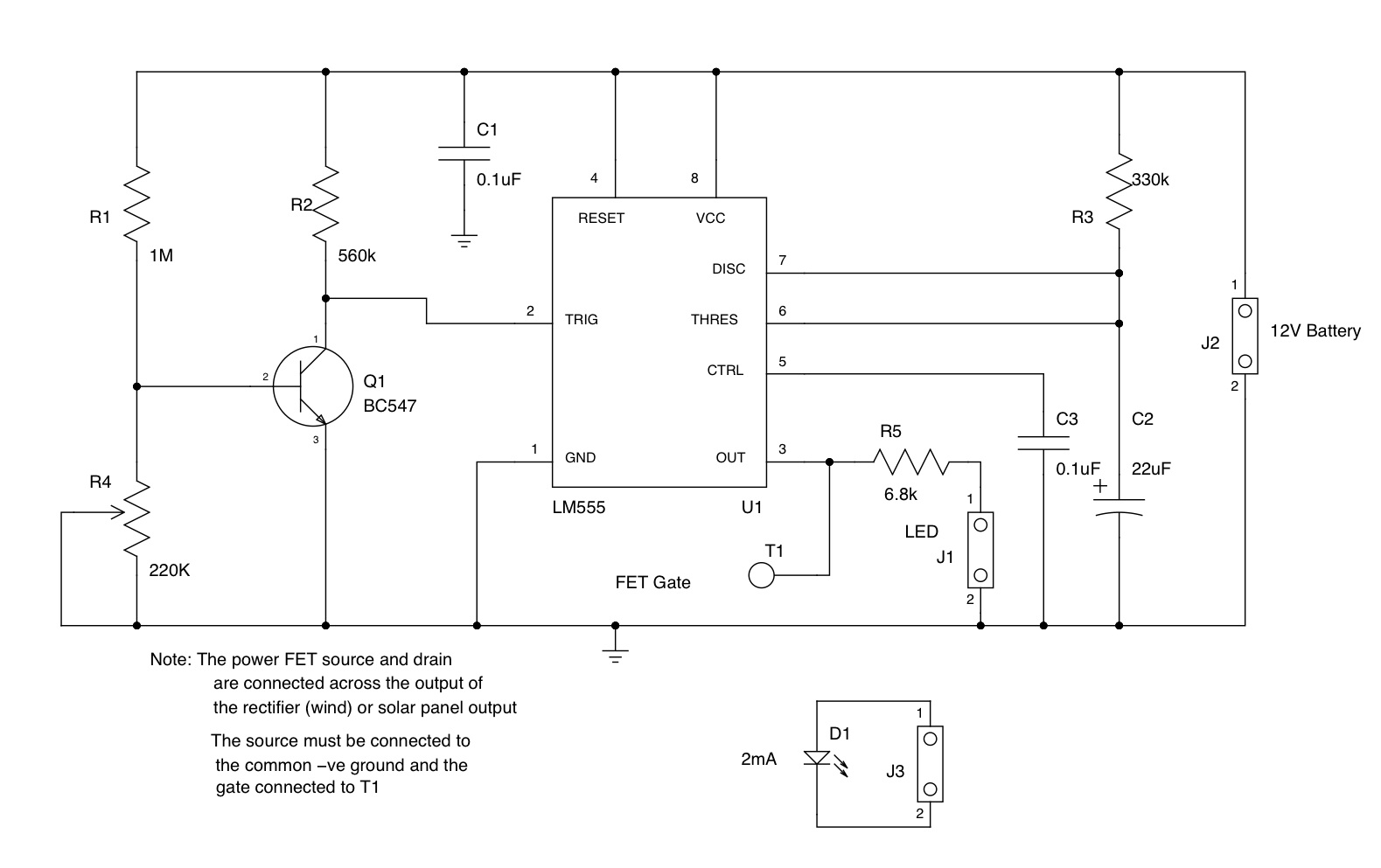
After considering several different types of shunt controller designs, I decided to go for a simple solution based around a 555 timer configured as a monostable. The monostable input monitors the terminal voltage of the battery. When it reaches threshold value, the monostable will trigger with a pulse duration of about 5 seconds. This output is used to turn on a power FET which shorts the output of the wind-turbine. After the monostable resets, if the battery voltage has not fallen, it will re-trigger and the cycle repeats, with back-to-back short pulses used to turn on the shunt FET. In practice, the FET can be considered to be permanently switched on in this mode.
Once the battery terminal voltage drops below the threshold (due to use), the monostable will not be re-triggered, the FET will switch off and normal charging will result.
Practical Considerations
The circuit that monitors the battery voltage will be permanently connected to the battery. For this reason, it must draw minimal current so as not to drain the battery it is monitoring!. The CMOS version of the 555 timer (ICM7555) is used in the circuit which has a maximum quiescent current of 300uA (typically 60uA). High resistor values were chosen throughout so it should be possible for the whole circuit to draw less than 400uA max (70uA typically).
Regulator Circuit Design
Having ironed out a few niggles with the electronics, it was time to put it all together and remove the rats nest of wires and crocodile clips that seem to be proliferating. I wanted to put the rectifier and regulator circuit in one enclosure with some metering to check all was working as expected. Other features that would be useful would be:
- A manual override to place a load on the turbine
- Be able to feed solar power generated power through the same regulator
- Possibly provide an auxhilliary dc input channel
- Be able to monitor battery voltage and charge current
- Be able to switch voltmeter to read input voltages on each channel
- Provide an indicator to show when the shunt is in operation
- Provide a readout of the speed of rotor rotation in RPM
This last point is a nice-to-have so I decided to keep it in mind but would not implement it in the first incarnation. Hopefully, I can add it to the system once the regulator is installed and working.
Regulator Construction
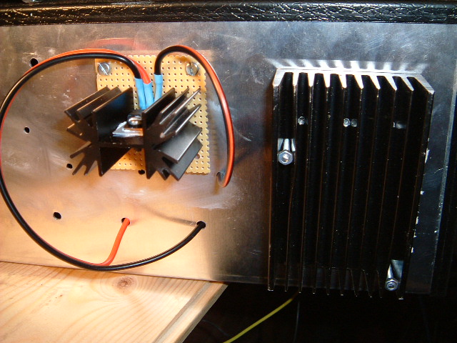
The regulator circuit was constructed using veroboard. I will save building a pcb until I see how it performs. I had an aluminum case that was earmarked for a power supply some time ago which looked like a good candidate to house the circuitry. As, the enclosure was fairly large, it looked possible to drop the rectifier circuit as-is directly into it without the need to rebuild it. There was room on the front-panel to mount a voltmeter and an ammeter which could be used to check the outgoing charge to the battery. It was possible to make provision for 3 input 'channels' which allowed for the adding of a solar panel input and another (DC) input. There are times (ie is very high wind conditions) that it is useful to be able to short the output from the power generating source (eg wind turbine) via a suitable resistor. Although the regulator should cater for this, sometimes it is useful to be able to do this manually.
Although the turbine is only rated at 12 Watts, it is surprising how much heat can be generated when dumping current (either through a load resistor or through a transistor). For this reason, heatsinking was used extensively in the design. The complete circuit is shown below.
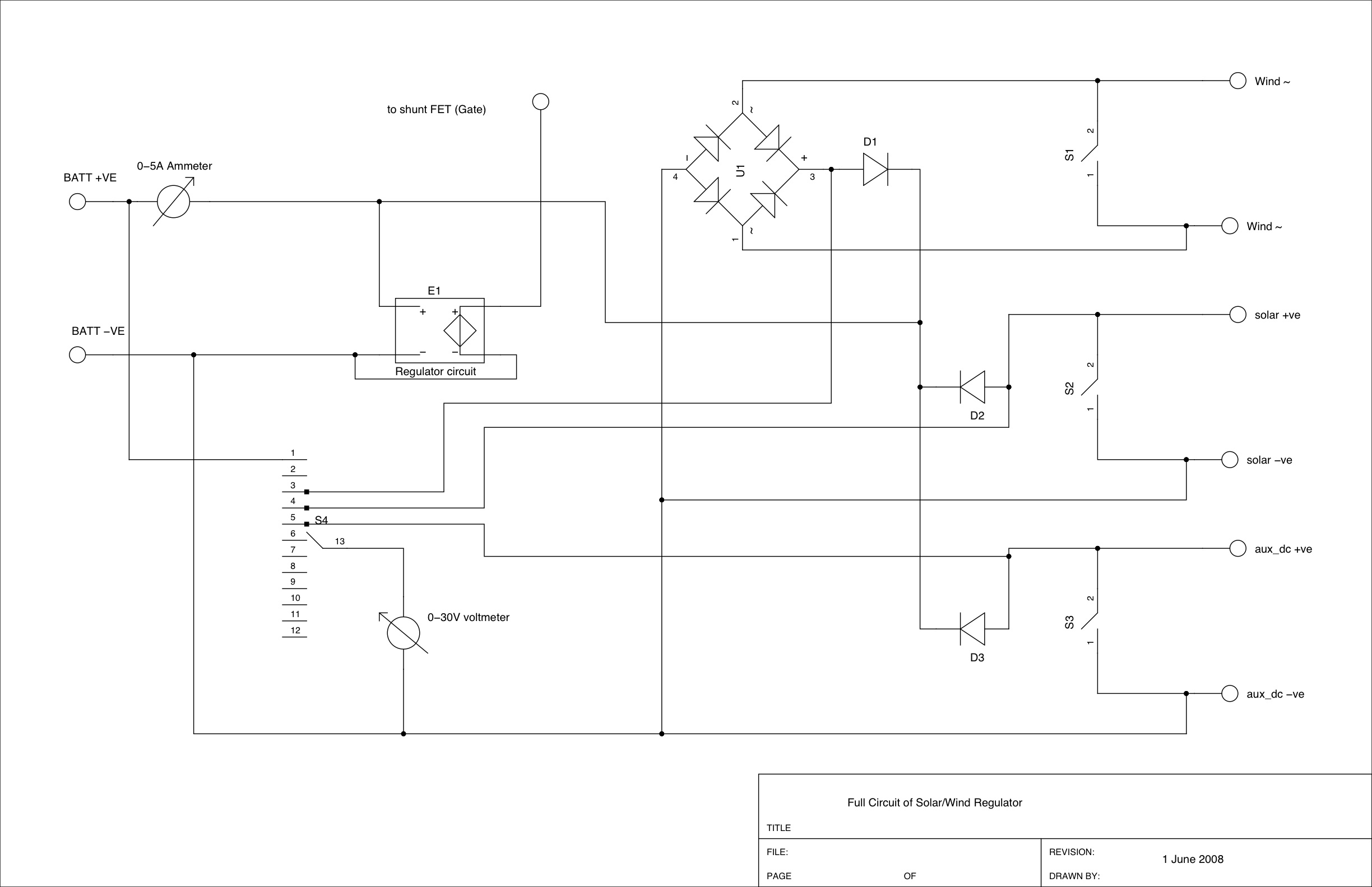
The voltmeter can be switched to measure the input from each channel, the regulator output or the battery voltage. As can be seen from the circuit, steering diodes are used to feed all three input channels into the regulator circuit. To reduce voltage drops, these were schottkey diodes rated at 8A each and were bolted directly onto the aluminum case to provide a heatsink. Mylar washers and heatsink compound was used to insulate the diodes from the chassis.
The three load resistors were also bolted to the chassis and could be used to 'load' an input channel by operating a switch on the front panel.
Yesterday saw gale-force winds and as all my batteries were fully charged, I turned on the load switch as the regulator has not ben fully installed yet. Although this has worked fine in other situations, I found the rotor was still cranking round at high speed and the output of the rectifier was hitting 30V with no battery connected. This means the turbine is generating in excess of my target 12Watts and the resistor is not low enough for the job. I want the switch to totally disable the turbine so have decided to use the switch to simply short the turbine rather than pass the output through a load.
The FET within the regulator circuit could in theory pass the sum of all three input channels to ground if connected to a fully charged battery. Each input channel is rated at approximately 1 amp so this transistor may need to shunt 3A. The FET used was rated at 10A continuous and mounted on a large amplifier heatsink at the rear of the enclosure. The thermal resistance of the heatsink was 1.8 degs/Watt so should be more than adequate for the job.
The Regulator in Action
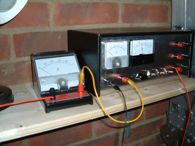
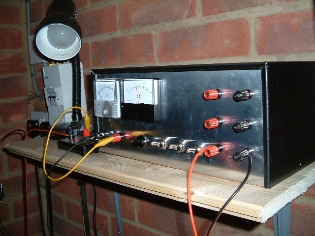
I finally finished the regulator and plumbed it into the wind-turbine. I must say that getting rid of all the long cables and crocodile clips is liberating, I don't feel to be walking past a bird's nest any more. The trim pot on the regulator was adjusted so that the circuit would trigger at approximately 13.5 volts. A couple of pictures showing the regulator enclosure are shown below. I pass the output through a more sensitive Ammeter for testing although this is not really necessary.
My batteries were sitting at a lower voltage than this so I had to wait for then to charge before I could see how the circuit behaved in practice. I'm pleased to say that it works exceptionally well. When the battery gets charged, the terminal voltage rises. When it is approaching full charge, a strong gust (hence current surge) will cause the terminal voltage to exceed 13.5 volts. The circuit clicks in and the wind-turbine is shorted out, preventing current from being passed to the battery. The voltage on the battery drops slowly during this time. The turbine blades have started to wind down in the meantime (shorted out) and are rotating at something less than 60 RPM by the time the regulator monostable finishes its timing cycle. The timing cycle of 5-6 secs is long enough that the battery voltage has dropped to about 13.2v so the monostable does not re-trigger. The wind-turbine blades then starts to speed up again and when the battery voltage hits 13.5 volts again, the cycle repeats. For a constant wind, this results in the blades starting, winding up for about 5 seconds, then slowing down for 5 seconds and then speeding up again. This is good news as far as the FET goes as it not constantly 'on' and having to disipate heat. A solar panel would not be so forgiving.
When the wind is more variable, the battery voltage will slowly drop and the regulator will only kick in during strong gusts or if a prolonged slow charge in a light wind results in the trigger threshold being exceeded. If a load is drawn from the battery during charging, the terminal voltage rises less quickly with gusty conditions and regulator kicks in far less frequently (as expected).
The regular circuit appears to work very well in varied wind and load conditions. The whole system will need beefing up if I were to connect a larger turbine or a large solar panel to it, but the design is sound. It is just a case of scaling up components and wiring in that case
Adding a Solar Panel
As the summer arrived, I decided to upgrade my solar panels to get some more useful power to fill in the gaps during low-wind conditions. I increased the solar input from 10W to 70 Watts so the amount of power my little wind-turbine generates will probably get lost in the noise now. That should be rectified when the larger wind turbine is installed.
Rather than using one FET to dump all of the load from both wind-turbine and solar panel, it seemed better to add another device to cater for the solar panel. This reduces the power disapation in one FET and spreads the load across two of them. The same regulator circuit was used as before, monitoring the battery output voltage. An extra FET (heatsinked) was bolted to the back of the regulator case and an an extra feed taken from the output of the regulator to feed its gate. The source and drain of the new device were connected across the output of the solar panel. This means both FETs are turned on when the battery reaches its maximum threshold voltage.
The regulator behaves very well with the solar load. A couple of sunny days meant the batteries were topped up quickly. It is interesting to note how the regulator behaves depending on the amount of charge going into the battery.
Towards dusk, about 300mA of charge was being generated by the solar panel. This caused the battery voltage to rise slowly until it reached the threshold (adjusted to 13.8v now). The regulator then kicked in and shorted the solar output for 6 seconds and during that time the battery voltage dropped sufficiently for the circuit to start diverting charge back into the battery. The battery was therefore kept topped up with short (about 2 second) bursts of 300mA before the regulator cut in and the battery voltage fluctuated between about 13.5v and 13.8v
When there was much more charge available (greater than 1 amp), The battery voltage looks to sit at a lower value (about 13.0 v) and the regulator is constantly in discharge mode. I presume this is because of very short charge pulses that the meters do not register which push it over the 13.8v threshold. It is interesting that the higher the charge rate, the lower the battery terminal voltage. However, this is a fairly artificial test as no load was connected to the battery. As more charge is being taken from the battery, these spikes will have less effect on the operation of the regulator.
Overall, the regulator works exceedingly well for such a simple design.
03 June 2008
| Home | Contents | Start | Prev | 1 | 2 | 3 | 4 | 5 | 6 | 7 | 8 | 9 | Next |