| Home | Contents | Start | Prev | 1 | 2 | 3 | 4 | 5 | 6 | 7 | 8 | 9 | Next |
12 Watt wind turbine blade construction
Turbine Blades
The next issue was deciding what size of blade to use, and then work out how to make them. The alternator just built is easy to turn under no-load. As more current is drawn, it gets harder. The larger the blades, the more turning force can be gleaned from the wind, which results in more electrical power being generated. A bit of research uncovered:
- The larger the blade, the more torque generated
- A Larger blade will rotate more slowly
- More blades give more torque but rotate slower
This is why the wind turbines use in America during the 1800s had many blades. They required a lot of torque to operate a mechanical pump and consequently revolved quite slowly. It appears that three blades seems to be a good compromise and if it is good enough for a commercial turbine, I'm sure it will be fine for me.
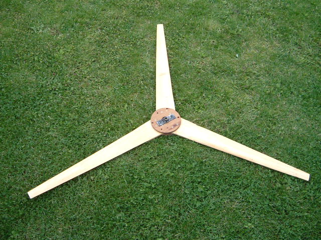
My turbine is quite small and all my testing has been at 220 rpm. This is by no means fast in terms of an alternator but is somewhat faster than many larger turbines. At this stage, I do not really know the speed these things can pick up to so I have to take a bit of a stab in the dark as to blade sizing. I've taken an educated guess at going for a 1.2 metre diameter blade, reasoning that this should give me the torque required, rotate quickly enough in low winds, and is not so large as to annoy neighbours. I need to start somewhere so this is my groundstick and may have to scale up or scale down based on actual results.
Obtaining blades of this size can be somewhat costly. Some research indicated that blades can be manufactured by cutting up plastic waste pipes or they can be carved from wood. Although using a waste-pipe would be easier to make, they are potentially more noisy as they are not true aerofoils. As this is the first turbine, I decided to carve the blades from wood, mainly to see if I could do it and also it would look less heath-robinson so possibly be more acceptable to the neighbourhood.
There are many designs for available for turbine blades but I opted to use those detailed at http://otherpower.com as I reasoned I could build those with the tools at my disposal. I took their design and scaled it down to suit my needs. The main obstacle with making the blades is that they are tapered both in width and their length. Frank, my father-in-law came to the rescue again and produced the blanks for me on a band saw. That just left me to carve the blades and produce an aerofoil. It is recommended that you use a draw-knife to cut blades but I found a hand-plane, a chisel, a shureform and a file were more than enough for the job, as the blades are quite small. When finished, I coated the blades with several layers of teak-oil although I will probably pain them before finally mounting them on the machine. The finished article is shown below
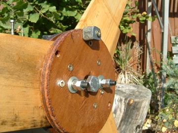
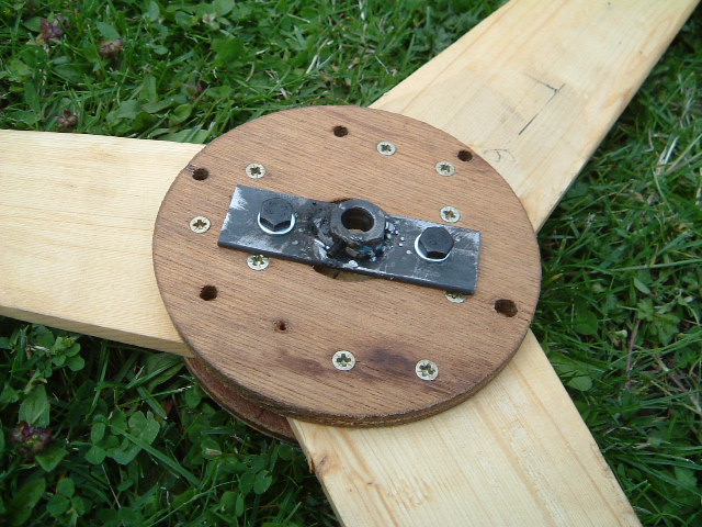
After carving the blades, they were sandwiched between two plywood disks and a mounting bracket made by welding a 10mm bolt to a length of steel and then tapping the bolt to take a grub-screw. As the last thing we want is for the blades to come loose, the grub screw will be augmented by glue and collets when finally mounted.
Making the Tower
As this is only an experimental affair, I have no plans for making a permanent, full blown tower. My location does not lend itself well to wind turbines so I decided to go for a small tower that I could easily raise and lower to facilitate testing and tweaking. I obtained a 4 metre length of 32mm steel pipe with 3mm wall thickness which I think will be ample for the job. The 32mm thickness was somewhat dictated by other pieces of metal I had lying about when making the frame for the turbine itself. 'Tower' seems a rather grand name for a short length of rusty steel pipe, but I had to call it something.
The most useful arrangement was to mount the the pole against a 6ft wall at one side of the garden. My plan is to drill bolts right through the wall and use something like 3 munson rings to clamp the tower in place. Rather than faffing around on ladders, it seemed a good idea to hinge the tower so I could unfasten it from the wall and fold it down towards the ground. This way, it would be possible to make adjustments and try out different turbine designs on the same tower and then just push it up through 90 degrees and clamp it to the wall again.
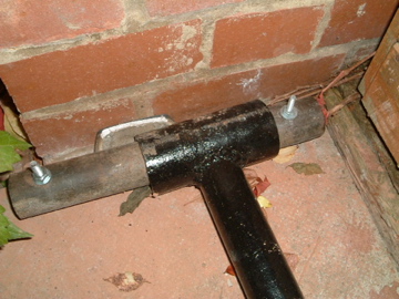
After considering a few options, one solution to create a 'hinge' was to weld the pole to the centre of a short length of pipe at right angles. It was then possible to slide a smaller pipe through the fat pipe and attach both ends to something solid. The fat pipe would then rotate around the smaller one. This has to be approached with some care as I used some scaffold pole for the hinge which was galvanized. Welding galvanized steel produces some nasty fumes (eg cyanide) so it's best to use an angle-grinder/wire brush to remove the galvanization before welding.The basic 'hinge' parts are shown below prior to welding together.
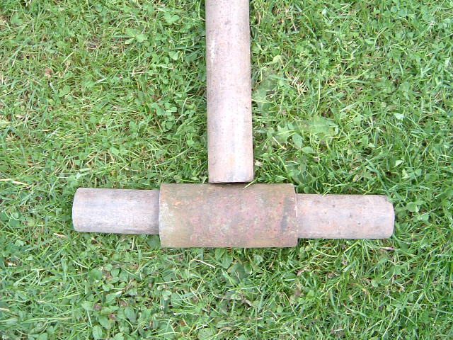
Rather than welding directly to the tower, the 'upright' was a pole whose inside diameter was just large enough to accommodate the 32mm diameter pole (an interference fit). This was done so I could work on the hinge independently of the pole. It also gave the option to use a longer replacement pole in the future. Two cuts were made in the fat pipe where the upright would sit, to give it a good mechanical seat, prior to welding in position.
The hinge itself is not really under strain when the tower is in use, all the weight will be vertically down through the pole, there should be no twisting/turning forces as these will be taken up by the tower mounting brackets further up the wall. When mounting the centre-pipe for the hinge, I wanted the load to be spread between the centre-pipe and the fat outer pipe which was easily achieved as the centre-pipe is quite a loose fit in the fat pipe. Now seemed a good time to clean up all the rusty steel and paint it. The tower pole will get the same treatments as it has been lying around in the garden rusting for several weeks now. Any exposed steel on the frame was also painted and wooden parts treated with teak-oil.
The ground where the base of the tower was to be placed was leveled as best as possible and packed down with sand. Two bolts were passed through the outer pipe and the whole assembly bolted through a paving slab placed over the leveled sand. Frank, my father-in-law stepped in to sort all this out which has been a great help to me. The hinge was then free to move through 90 degrees. The tower pole was pushed into the lower pipe and the tower raised to the vertical to make sure it was indeed vertical. The wall was marked out and made ready for drilling the tower mounting brackets.
Tower Wiring
The electrical power generated by the turbine needs to be brought down from the tower. The simplest solution is to bring it down the centre of the tower. I was concerned that as the machine spun around the tower, the wire would get horribly twisted but having read around on the internet, it appears this is not too much of an issue. I guess in calmer conditions the twist in the cable will tend to help the machine twist back again in slight gusts. I think slip-rings at the top of a tower is asking for trouble. A solution to consider in the future is to make use of the conductive properties of he tower itself perhaps ? - probably not idea in case the pole gets hit by lightening.
The problem with low voltage, high amperage power generation is resistive power loss. It is far better to use high voltage and low current although this is not really an option here
			Power disapated is: P = VI

			and Ohm's law states:V = IR

			therefore: P = I2R
Reworking the above, shows power is also given by V2/R, meaning the power disapation will fall for larger R. This is why the National Grid uses high voltage and low current. Anyway, all this waffle means that
we should try and keep resistance to a minimum when using low voltages and relatively large currents. Therefore the wire used in the tower should be low resistance, fat and flexible (ie expensive). I know this. I also know I have a roll of cheap insulated wire I have used to run around the garden to wire up my solar cells. It seems adequate so for now, it will have to do. When I move on to a more ambitious project, I will replace it with something more suitable. The cable was threaded through the top of the frame pole and down through the tower pole. A hole was made near the bottom (but above the pipe into which the pole fitted) and brought out.
The erection of the tower has been delayed somewhat due to some birds deciding to build a nest in the Ivy on the garage, right where the tower was due to go. There will be a small delay in proceedings....
Maintenance (December 2007)
Well, the turbine has been running for about 6 weeks and there have been some pretty violent winds lately. I recently noticed that the machine was turning much more slowly that it should be and I concluded that the electrics must have shorted out. I am very thankful to have built a hinged tower :-). Bringing the machine down for inspection showed that this was indeed the case. Where the cable had come up through the pole, it had twisted until it had snapped in two, just where it leaves the pole at the top of the machine. The cable coming from the coils has shorted out so that the turbine always was working into maximum load. I have fixed this temporarily with some extra-flexible wire and a chocolate block connector. However, I am reaping the rewards of using cheap cable so it is time to replace the main feeder cable with something rather more robust.
I took the opportunity to check that all bolts and grub screws were tight and that nothing was working loose. All seemed fine, but I was amazed at how rusty the exposed shaft had become. I had not painted this so will probably grease it when I replace the cable.
10-Jul-2007
| Home | Contents | Start | Prev | 1 | 2 | 3 | 4 | 5 | 6 | 7 | 8 | 9 | Next |