| Home | Contents | Start | Prev | 1 | 2 | 3 | 4 | 5 | 6 | 7 | 8 | 9 | Next |
Output Voltage Regulation
It appears that for the last 3 weeks, there has been no wind and the turbine has sat motionless and not producing any power whatsoever. However, my earlier tests showed that the machine can produce more voltage than required and it will be necessary to regulate the output suitably so it can charge car batteries safely.
Rectification
The first task is to rectify the output from the turbine to convert it from AC Volts to DC Volts. During testing, I used a single diode which gives a half-wave rectified output that has severe ripple. For the final version, I decided to use a standard full-wave rectifier circuit with a 4700uF (63V) reservoir capacitor. The circuit diagram is shown below:
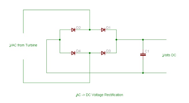
I am in two minds as to whether the reservoir capacitor is a good idea. It will smooth the output voltage and reduce droop but this may not be too important as the regulator should compensate for this further downstream. My main concern is that when the turbine starts up, it's output will pass through the diodes and into an 'empty' capacitor. The rate of change of voltage on startup will be greatest so the capacitor will have a low impedance. The net effect is a large load on the turbine when it is just spinning up, so it may not spin up at all in lower winds. I may find this is not a problem at all, but if start-up is affected, the capacitor will have to go.
I decided to build the rectifier and regulator as separate modules with the aim of eventually putting them both in the same enclosure. Keeping them separate for now allows each unit to be tested in isolation and makes swapping modules easier should it be necessary
Rectifier Construction
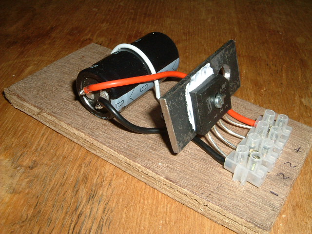
I happen to have a bridge rectifier encapsulated in an in-line package which is rated at 8 amps (when suitably heat sinked). As there are so few components involved, and due to the form-factor of the bridge rectifier, The whole circuit was built on using a chocolate-block connector mounted on a plywood backplate. I used a small length of steel strip left over from the tower construction as a heatsink which was bolted to the bridge rectifier (with suitable heatsink compound). I don't know the thermal transfer characteristics of this arrangement but I'm sure it is more than adequate for the job. If I find the rectifier gets too hot, I'll work out exactly what I need in the way of heatsinks, but that is for another day. The basic arrangement is shown below:
As luck would have it, this weekend brought winds which were ideal for testing a few things out. The new rectifier was put in place and I sat back and monitored a few things. With no load, the bridge rectified output gets up to nearly 40 volts in high winds although I did not let it rise any higher than that before applying a load.
I connected up to a 45AH battery that has been languishing with no charge for the last 3 weeks (thanks to no wind). The picture below shows the output voltage and charge current when the turbine is running at a good speed.
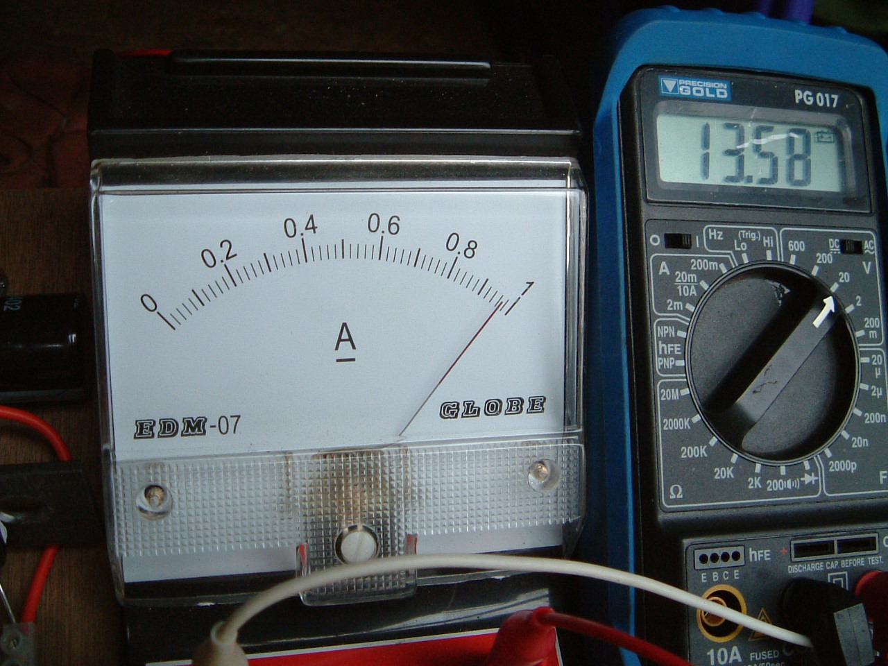
13.58v @ 1 Amp. This is giving me 13.58 * 1 = 13.58 Watts output power, in excess of my goal of 12 Watts, so I am very pleased with the results :-) My reservations about the smoothing capacitor seemed unfounded but it is windy at the moment, it may have an effect at border-line wind conditions.
I had left the system connected up overnight and found the battery terminal voltage had risen from 12.5v to 14.2v in the morning. The battery voltage was slowly creeping higher so I had to disconnect it from the turbine to prevent over charging it. I definatly need to build a voltage regulator as it seems a shame to have all this wind and have to disapate the extra power into a load.
4 Feb 2008