| Home | Contents | Start | Prev | 1 | 2 | 3 | 4 | 5 | 6 | 7 | 8 | 9 | 10 | 11 | Next |
Creating the stator for the 200 Watt machine
 |
Estimating output voltage |
Coil Selection and Output Voltage Estimation
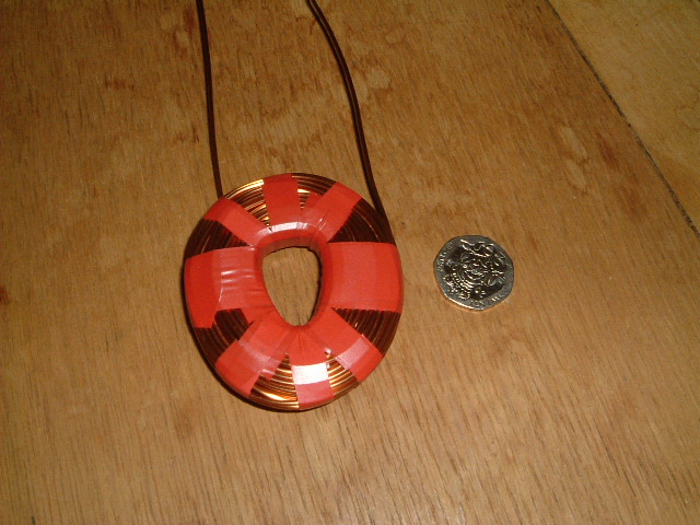
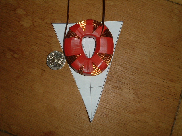
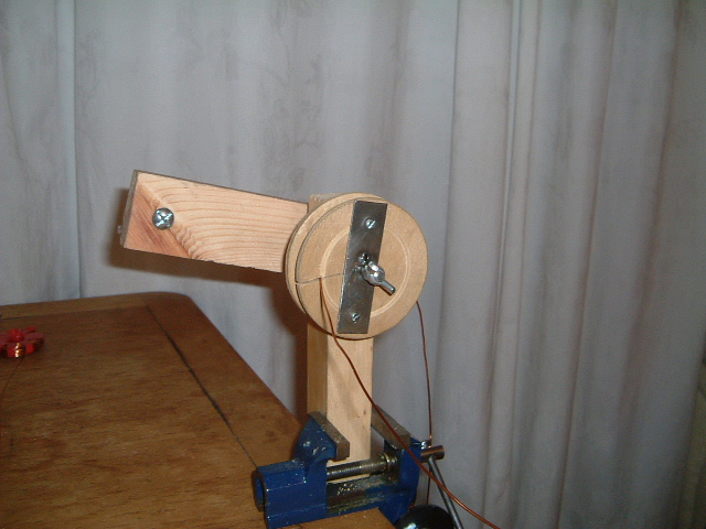
After drawing diagrams of the rotor and stator, it became apparent I could use much larger coils in this design as there was much more room to play with. I was keen to build a 3 phase machine and set about seeing if that was possible. In order to achieve this, a multiple of 3 coils were required in total. Since the coil wire was much thicker than the previous design, this would limit the number of turns I could get for a large number of small coils. Based on the size of the magnets and the geometry of the disk, it looked like 9 coils was the best compromise. I had to modify my coil winder to accept these larger coils and when this was done, I cut out a paper template of a disk segment 1/9 of the disk area. It turned out that the coils could only have 85 turns before they became too large to fit in the space provided.
Having created one test coil of 85 turns, it was time to break out the test harness to see what kind of voltage could be produced. The harness used a small 100mm disk and one of the new larger magnets with the test coil. I reasoned that as the magnet is turning on a smaller radius than the real machine, the magnet will be moving slower so if anything, will produce less voltage when testing than when mounted on the real disk. I believe the larger turbine will probably have larger blades and will rotate more slowly so I did my testing at 120 rpm this time. Results were:
Voltage generated for one coil and one magnet = 100mv
This was rather better than I was expecting and it could well be higher, this was an average value. From my earlier design, I can get a rough idea of the voltage generated per coil by multiplying up:
Voltage per coil with 24 magnets (2 rotors) = 24 * 100mv = 2.4 volts (ac)
If we went for a three phase design, we would have 3 coils in series per phase so:
voltage per phase = 3 * 2.4 = 7.2v
And if wired in 3 phase star, this will give the following voltage across phases:
Voltage across phases (star) = 1.7 * 7.2 = 12.24 volts (ac)(where 1.7 is the square root of 3).
Once rectified to dc, the voltage available will be:
12.34 * 1.414 - 1.4 = 16 Vdcwhere 1.414 = the square root of 2 and 1.4 = 2 diode drops in the rectifier.
Which, if anything, is a touch on the high side, but the voltage will get pulled down as the load current increases. Based on these calculations, the turbine should start producing 12 volts (dc) output at about 90rpm. Well, that is what these rough calculations are predicting, reality may have something else in store.
So, in theory, it looks possible to easily produce the required voltage at low RPMs with this design. How difficult it will be to turn the alternator will be a big factor and may require much larger blades (or more of them) to create the torque required. I can easily modify the mounting bracket on the blades I used for the 12 Watt design and use those as a starting point.
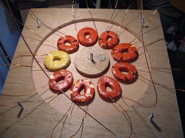
The remaining coils were wound using the coil-winder, producing 9 in total
The Stator Mold
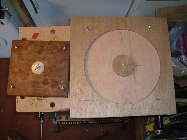
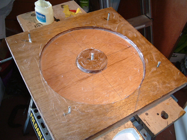
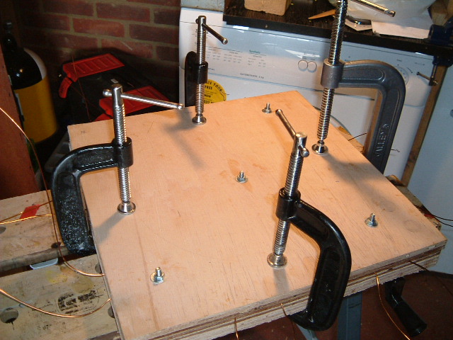
The design used for the 12 Watt stator worked pretty well so there was no reason to change it radically. Although this stator will have a larger diameter than the 12 Watt design, as it just has to support its own weight, I could see no reason to make the stator any thicker as that would increase the distance between the two rotors (reducing flux density) and require more resin and fibreglass to construct. So this stator was also going to be 12mm thick, this time with a diameter of 300mm. This may be slightly on the large side but gave extra room for mounting coil connections and stator mounting holes. However, it is important that the stator is flat and 12mm thick consistently so I decided to make the top and bottom of the mold out of 18mm plywood to ensure that nothing would bend when clamping it together.
The mold was made in a similar manner to that for the 12 watt design, the idea being it could be bolted together and easily dismantled to ease stator removal. They plywood was coated with teak oil to seal it. The 12 Watt design required me to line-up the coils by eye with markings on the base of the mold. This time, I decided to make the coils a snug fit so that they would slot in and not require lining up by eye. This meant the resin did not need to be transparent so I could use a filler in the resin to make it go further, as this stator will require a lot of resin. The picture below shows the finished mold, comparing it's size to the 12 Watt turbine mold.
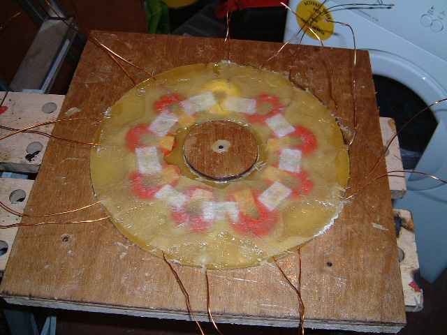
Next, the coils were added to mold, the bottom of which had been marked out so the coils will be in the right positions relative to the rotor magnets.
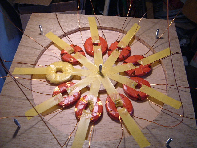
When the coils were correctly aligned, they were fixed in position using electrical tape:
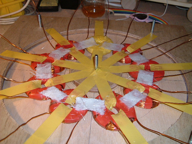
Fiberglass matting bridges were placed between the coils and smothered with superglue until they set hard:
The coils were removed from the mold once the glue had dried. To enable the stator to be removed easily from the mold when it had set, the mold was liberally coated with vaseline. A bit of a messy job but as it turned out, well worth the effort.
I mixed up some resin and added it to the mold. Then a layer of fibreglass, then the coils were replaced. More resin, then another layer of fibreglass and more resin. This large stator requires a lot of resin so I mixed 40% talcum powder to the mix. However, I was still rather short on resin, and had slightly less than I really needed - doh !. I had no choice but to clamp the mold shut and hope there was enough resin to go round.
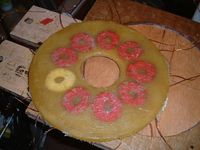
Less hardener had been added than recommended as this gives a slower setting time to minimize contraction. I left the stator overnight and came back to it wondering what I was likely to see when dismantling the mold. As no resin at squeezed out through the sides of the mold, I was expecting the coils not to have been covered properly but was hoping there was enough resin to hold everything in place ok. The mold came apart very easily and the stator popped out quite easily. The central 'island' needed a little intimidation but I had to use little force to get the cooked stator out of the mold. And here is the result:
As you can see, things could have been a lot worse! In fact, I was pleasantly surprised by the result. There are some large craters in the stator but they are near the edge and the centre so the coils are well covered. I was able to fixup the edges with some wood glue as filler and although the craters will male mounting bolts a little tricky, this is quite a serviceable stator :-)
The underside of the mold came out very smooth and consistent as there was plenty of resin to go round there:
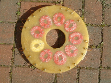
All that remained was to tidy the edges up a bit with sandpaper and put the terminal connections bolts through the stator. There will be 18 in this design, a bit on the excessive side but I still feel that bringing all the coils out to the edge gives greatest flexibility. It gives the option of single-phase wiring, or star or delta three-phase. I guess I can adjust depending on the output of the machine.
Since the stator has some craters, I had to place the connection terminals and stator mounting holes where I could. The coil connections were made using 4mm brass bolts and washers. The stator mounting holes were 6mm.
And here is the final stator with all the coil connections brought out to the terminals at the edge of the stator. As with the 12 Watt design, I looped them over the edge of stator and connected them on the other side, This gives a bit of leeway in case it is necessary to remake the connection because of a wire snapping under one of the nuts - it is always possible to connect on the other side.
| Home | Contents | Start | Prev | 1 | 2 | 3 | 4 | 5 | 6 | 7 | 8 | 9 | 10 | 11 | Next |