| Home | Contents | Start | Prev | 1 | 2 | 3 | 4 | 5 | 6 | 7 | 8 | 9 | 10 | 11 | Next |
Initial Assembly
Although I had originally drilled and tapped some 6mm holes through the sprocket to aid assembly/disassembly, I considered this rather an overkill. As a second plan, the holes in the second rotor disk (the one without the sprocket) were drilled and tapped for an 8mm thread. This way 4 jacking bolts could be used to lower, raise the second rotor onto the first and sandwich the stator between them. The jacking bolts would push against the sprocket for leverage.
200mm jacking bolts were made by cutting some allthread and using two nuts to make a 'bolt-head'
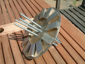
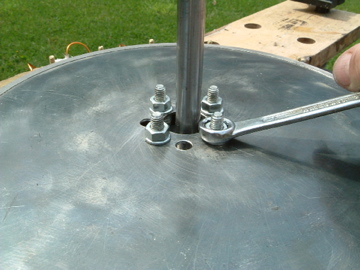
At first, I tried assembling the alternator in-place on the frame. This did not really work very well as the jacking bolts get caught on the frame and the rotors try magnetically clamping themselves to any part of the frame they can find. A better solution was to remove the assembly from the frame and assemble it on the bench. It is necessary to keep the rotor in place as the sprocket-rotor needs fixing in the right position on the rotor (grubscrew) before adding the stator and second rotor.
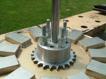
The stator is placed over the sprocket rotor
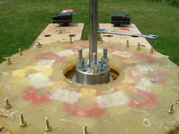
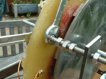
Lowering the second rotor using the jacking bolts.
When the second rotor had been lowered and bolted into place, the stator was sandwiched so tightly the rotors would not turn. Not enough clearance between the disks so off the rotor came again. The jacking bolts were worth all the effort now, it would have been impossible to prise the rotors off the stator otherwise, the magnetic attraction is very strong.
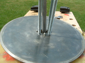
Two nuts and several spacers were added to the sprocket 6mm mounting bolts, giving suitable clearance on top of the sprocket thickness and the rotors and stators were reassembled.
As can be seen, the total clearance is about 6mm which should give 3mm per rotor. I little more than I originally intended but I can shave more off this later if necessary.
![]()
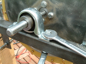
The assembly was then threaded through the bearings and the bearings were bolted down.
Next the stator was attached to the stator brackets using stainless steel (A4) hardware. It was bolted to the stator first and then adjusted using the nuts on the bracket.
Initial voltage tests
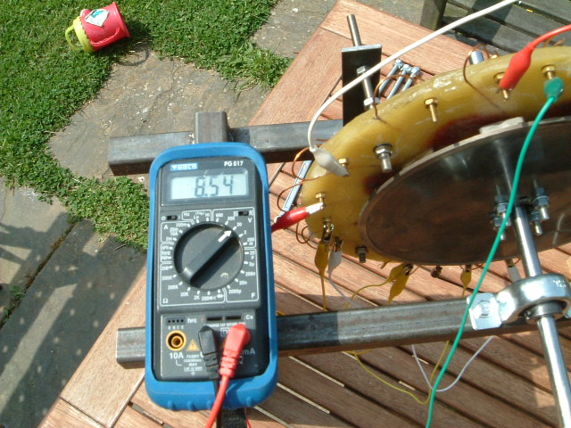
Now both rotors were in place, I was hoping to see a higher output from the machine when it was rotated. 3 coils were connected in series and the machine rotated at approx 90 RPM.
I measured one coil and was seeing about 1.7 volts
If wired in single-phase, this will give:
	1.7 * 9 = 15.3v.
	After rectification, this would give: 15.3 * SQRT(2) = 20.4 volts.
If wired as a 3 phase (star) machine, this would give:
1.7 * 3  = 5.1 v per phase.

Inter-phase voltage = 5.1 * SQRT(3) = 8.8v

After rectification: 8.8 *SQRT(2) = 12.5 volts.
After wiring the phases in star, I was seeing the voltage I expected across the phases:
Three phase is more power efficient, but the turbine will need to be rotating faster to generate usable power. Due to the larger weight of the rotors, this will probably act in my favour as once rotating, the momentum of rotors may prevent the machine from stalling once load is applied. If I went for single-phase, the machine would generate useful power at a very low rpm but this may cause the blades to stall just as they are starting.
I feel I'll stick to my original plan of wiring in three-phase (star) although it may require the blades to be turning at 120-180 rpm before they start to charge. At this stage I am unsure what kind of speed the larger blades will get up to, if they can rotate at several hundred rpm on no-load, all should be ok. It will also be an education to see how the greater blade/rotor assembly effects the cutin of the machine. As each stator coil connection is brought out to a connection, I have lots of options open to me.
| Home | Contents | Start | Prev | 1 | 2 | 3 | 4 | 5 | 6 | 7 | 8 | 9 | 10 | 11 | Next |