| Home | Contents | Start | Prev | 1 | 2 | 3 | 4 | 5 | 6 | 7 | 8 | 9 | 10 | 11 | Next |
Assembly and Testing
3 Phase Wiring
Now the stator is complete and mounted correctly, it was time to wire the machine for 3 phase operation. As all the coil connections are brought out to the edge of the stator, this gives lots of flexibility, even if it is somewhat time consuming to change from 3-phase to single phase or vice-versa. Initial tests have shown that the blades need to be turning at about 180 RPM to start generating useful power. Each phase was made by wiring every third coil (120 degrees apart) in series and bringing the two ends out to a connector mounted on the stator frame.
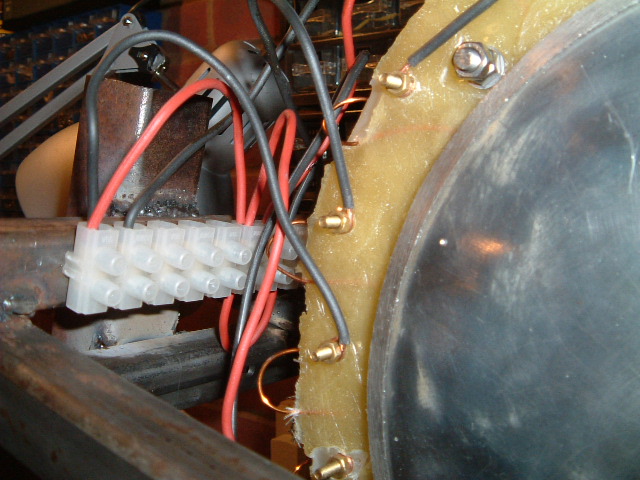
Ideally, Each phase should be wired in a different colour but as I only had black and red wire, two colours would have to do!. The 'ends' of each coil were wired together (in star) at the connector. Measuring across an individual coil and rotating the shaft at about 90 RPM gave a voltage of about 1.6v rms. Measuring across any two phases gave about 8V rms. This is more or less as expected for 3-phase:
	1.6 v per coil.

	For 3 coils in series: 3 * 1.6 = 4.8V rms.

	Voltage across star phases = 4.8  * SQRT(3) = 8.3 V rms.
It was finally time to remove the frame from its wooden support and mount it on a steel pole. The easiest solution would be to weld a round steel pipe (that would fit over the 'tower' pole) directly to the frame. Unfortunatley, my tower (at 4 metres) is not quite high enough so that with the longer blades it will be too close to a building roof. Although it will clear the roof, I suspect it will not be clear of the turbulence close to the roof surface. The 12 Watt turbine had a round pole welded end-to-end with a square pole to give some extra height and although this worked well, threading cables was difficult.
The solution I use this time was to weld the round pipe lengthwise with an offset to the round pipe. This gives the extra height required and will make threading of cables easier as they will not need to go through the square tube. A picture is worth a thousand words:

This arrangement was welded to the frame so the round pipe was on the inside with the aim of trying to balance some of the weight, either side of the pivot.

The blades and hub were mounted on the machine. As it turns out, the rotor assembly is not perfectly centred and the blades are not identical so it is necessary to balance the whole assembly when the blades are mounted. This is described in the 12 Watt turbine pages but essentially I was looking for neutral blades, they should not always rest in one position because something is off-balance. The blade assembly was mounted in such a way it should offset the rotor errors and I found that the machine was perfectly balanced without the need to add extra weights to blade hubs. I was lucky this time :-)
Now all the bolts were tightened, locking bolts added and everything was ready for a test-run on the pole. I have not built a 3 phase rectifier yet but I hope to get some idea of the AC performance. As luck would have it, the following days were very windy which would allow me to find the maximum kind of output that I could get from the machine. However, as this is a much heavy machine, has large magnets and larger untested blades, I thought better of it and will wait until there is a more reasonable windspeed before erecting the machine. Hopefully, I should have been able to build the rectifier assembly by then and then be able to get an idea of real charge capacity.
The Maiden Test Flight
I accidentally broke one of the wooden blades of the 12 watt turbine while the pole was down and as the 200 Watt design was ready I decided to give it a bash to see how well the blades worked. Wiring on the new design was much easier although the whole assembly is very heavy. I shorted the phases out (at the ground-end) and raised the machine on the pole. Initial observations were:
- The tail boom may not be long enough. The machine looked to be having difficulty turning into the wind even though the tail was furling in large gusts. This could be because the pipe making up the yaw bearing is quite rusty inside and when the surface rust has been worn away, it will rotate more easily. Regreasing the pole definitely helped the situation so I'll not change the design until it has bedded in.
- The blades started turning easily enough once the short from the phases was removed. Although elegant in their way, they make the machine look flimsy and the started to bend back towards the pole in higher winds.
- The 2 metre blades do not look too out-of-place but I think if I went any larger, it would become an issue with neighbours (and perhaps rightly so).
- Usable voltage seems to be generated at a lower speed of rotation (as designed) and 11V (rms) was measured across two phases at approximately 180 RPM. The maximum I observed was 15.5v rms before the experiment was terminated.
From these results, we can see that the voltage (after rectification) would be:
	For 11v:    11 * SQRT(2) =    15.5 v

	For 15.5v:  15.5 * SQRT(2) =  21.9 v
These results were obtained at lower speeds of rotation than the 12 Watt design but the wind was quite gusty so I would like to know if the blades will have enough torque to turn the rotors at lower windspeeds.
As the wind picked up, so did the speed of rotation and plastic blades bent back and the tips started to hit the pole, eventually jamming against the pole so I brought the machine down again to inspect the damage. The plastic had bent back where it was bolted to the blade hub so in any large wind, they would be as good as useless. So, the blades had looked flimsy and they were flimsy. I could beef them up by using thicker pipework or even using double-layers. However, I believe you need to over-engineer everything to do with wind turbines so I think it is time to get out my wood-working tools and make some wooden blades again. These should be much stronger and better suited for the job.
| Home | Contents | Start | Prev | 1 | 2 | 3 | 4 | 5 | 6 | 7 | 8 | 9 | 10 | 11 | Next |