| Home | Contents | Start | Prev | 1 | 2 | 3 | 4 | 5 | 6 | 7 | 8 | 9 | 10 | 11 | Next |
Blade Manufacture (Again)
Types of Blades
Well, I learned from my mistake of trying to take a shortcut to producing turbine blades. The plastic waste pipes were not strong enough for the job. This is in part due to the size and thickness of the raw material, the blades could have been wider and made from thicker material. However, such pipe was not readily available at my local DIY store and I have doubts about the strength and durability of PVC pipe. It will certainly stand up to the snow and rain, but may become brittle in the sun and may bend in a large wind. That said, I believe these blades may be perfectly suitable for a smaller machine, in fact I might create some for the 12 design as that is out of action at the moment.
In order to save time, I have considered making the blades from fibreglass. This would require making one blade out of wood, then making a fibreglass mould around it (probably in two sections). They I could use it to make as many blades as I could eat. However, I believe the time, effort and materials required would mean it would take even longer to produce than wooden ones.
It may be possible to produce several aerofoil 'formers' - cross sectional shapes out of plywood, connect them together with wire to produce a wing 'frame' and then cover the lot with fibreglass (pretty much like building wing models from matchsticks and brown paper like I did as a boy).. I'll ponder all these possibilities and maybe revisit blade manufacturing techniques later.
Incidentally, with the dollar being very weak against the pound, it is becoming economical to buy prebuilt fibreglass blades from the states and import them! If I break another wooden blade, I might try this avenue but for now, I will go with wood.
Wooden blades have served me well previously, so it was time to reach for the plane and chisel. Wooden blade manufacture is not onerous, just time-consuming. With a young family, time is something I am short on so it may take me some time to produce the finished article.
I did not detail the construction of the blades for the 12 watt turbine design which followed the same steps described here. I've documented the outline of the process here.
Blade Design
I am coming to the conclusion, that provided the blades are pitched to the wind, you could use set of wooden spoons and get something to rotate in a suitably strong wind. After all, I just had some plastic drain-pipes turning my alternator! However, it seems that some form of taper and a reduction in blade thickness towards the tip will reduce noise and provide a lighter, more responsive blade. Remember the aim is to get the turbine rotation in low wind speeds. An aerofoil at the back of the blade may not be necessary but as speed of rotation increases, it will help the blade fly properly. If designing a commercial wind-turbine, all these factors will need more attention but lets put things in perspective, this is a homemade turbine, welded together from argicultural-size steel components!
The blade design I used for the 12 Watt turbine came from otherpower and I mearley scaled things down for my design. These blades were excellent so I decided to use the same design suitably scaled for the 200 Watt design. The only dimension I needed to fix was blade-length which was 1 metre. The scaled-down rectangular size of wood I needed to start from turned out to be:
1000mm x 125mm x 25mmUnfortunately, when scouring a couple of DIY stores, I found 125mm x 25mm was not a 'standard' size of timber and as I don't have ready access to power woodworking tools, I decided to modify the blade design to suit wood that was available.
The best compromise I could find was wood that was 140mm x 18mm. As the thickness is considerably less than I required, I decided to make the blades wider. So my blades will have less pitch and greater width and may look a bit short and fat. I hope the lack of pitch will not be too detrimental, but the blades for the 12 Watt design had little pitch and they worked fine. I hope the wider blades will give more torque at the expense of some speed of rotation. OK, agreed, all a little wet-finger-in-the air but I believe it is better to build something than spend too much time pondering optimal solutions. Its a lot easier to modify a working system than getting the system working in the first place.
Blade Manufacturing Steps
There are several steps required and they are carried out in the following order:
- Cut blade to desired length
- Cut taper in the blade width
- Cut taper in blade thickness
- Cut the blade pitch (angle of attack)
- Create aerofoil shape
- Cut blade ends so they fit together snugly
- Fix blades together on a hub
- Mount bracket to attach hub to alternator shaft
- Balance the blades
Note that wind-turbine blades are the reverse of propellors, their aim is to slow the wind-down and generate energy in doing so. These blades are pretty flat on the windward side, with a suitable pitch (angle of attack) and have the aerofoil at the back of the blade.
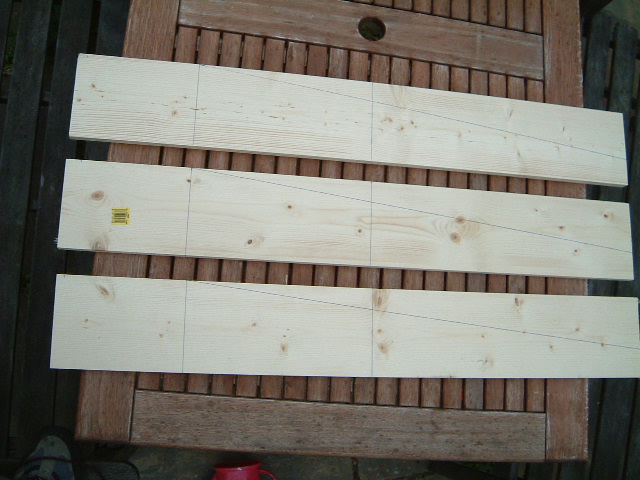
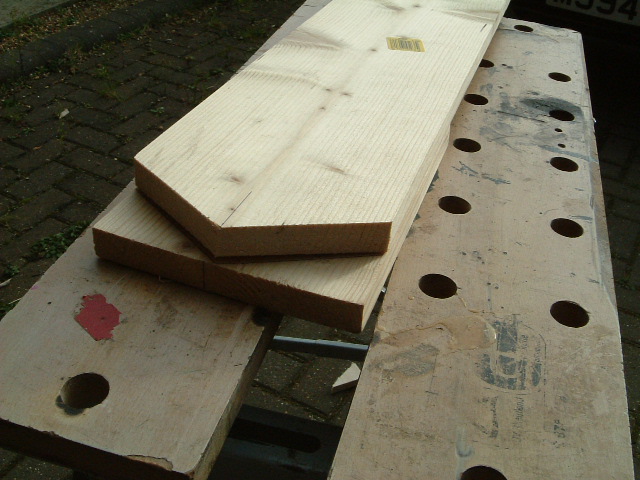
The blade has to be tapered both in length and thickness. Here are the blanks I started with, marked out and ready for cutting. They are 1000mm x 140 mm x 18mm in size. The blade tips are 50mm wide.
Cutting the tapers
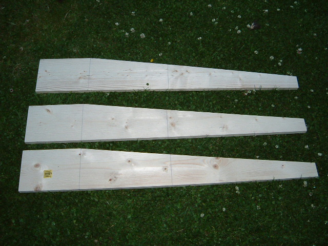
And here they are after cutting the taper in width. Note the taper is the whole width of the usable blade, there is no 'straight' part prior to the taper commencing. This makes blade manufacture easier and makes marking out easier. The blades 'start' 200mm along their length to give room for mounting on a hub.
Now it was necessary to to make the blade tapered in thickness. The tips of the blades were to be 4.5mm thick. I drew a line along the edge of the blade back to the 200mm mark. This means the blades are 18mm thick at the hub and 4.5 mm thick at the tip. Each blade was cut width-wise down to this line prior to starting to chisel out the excess wood.
On both edges, cuts were made with a chisel to prevent splitting the wood at the edges.
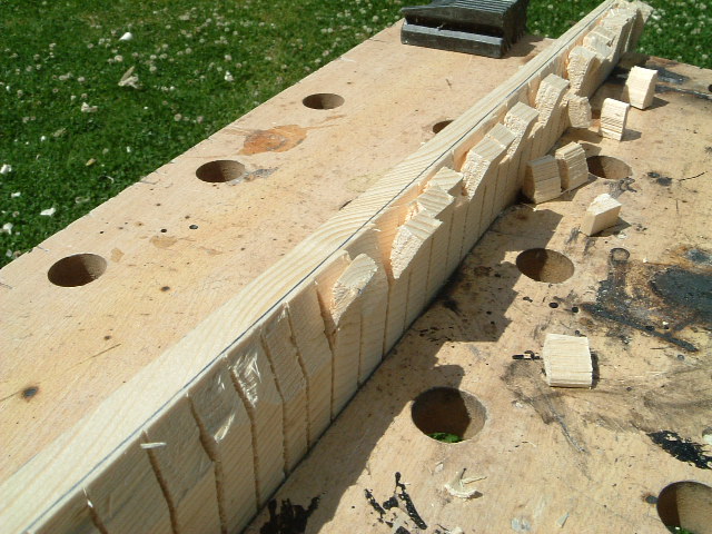
Then the whole blade-width was chiselled to remove the excess wood. When the wood was removed down to the bottom of the saw-cuts, a hand-plane was used to clean things up and bring the thickness down to the line. A shureform (rasp) was useful to help with some of the knots although the hand-plane was suitable for most of the work. A quick run over with sandpaper left me with three blanks of tapered width and thickness. Now I could start cutting the blade pitch and then finish off with an aerofoil.
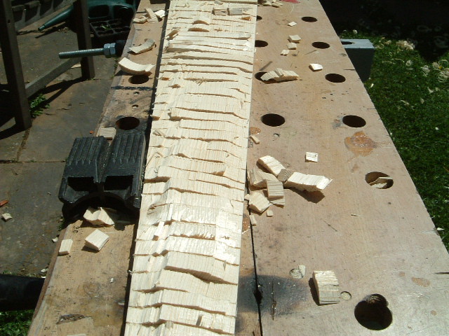
Cutting the pitch
It is now necessary to cut the pitch into the blades. Due to the tapering of the wood in both width and thickness, this gives a kind of 'twist' to the finished blade, the pitch being greatest at hub, and gradually reducing towards the tip.
The pitch is cut into what will be the 'front' of the blade, with an angle that extends from the leading edge to the trailing edge. The trailing edge is the one with the taper. On the trailing edge of the blade, measure down 3mm at the tip and draw a line down to where the 200mm mark meets the edge of the board. Wood needs to removed from the front of the blade, at an angle until it meets this line. The leading edge has no wood removed, and progressively more it removed towards the trailing edge. At the 200mm mark, this means we remove almost 17mm at the trailing edge (leaving just over 1mm for some strength) while at the tip, we remove 4.5 - 3mm = 1.5mm.
At the 200mm line (hub), this will result in a blade pitch of:
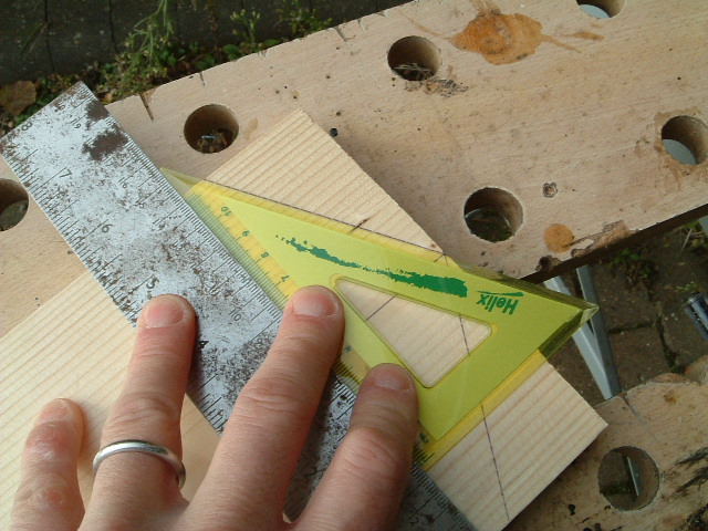
   tan-1(17/140) = 6.9 degrees.

and at the tip:

   tan-1(3/50) = 3.4 degrees.
I believe 4 to 6 degrees is about 'normal' for the pitch on a wind turbine blade so in the centre of the blade, we are just about spot-on. This picture shows the blade pitch at the hub-end of the blade.
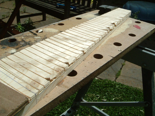
I prefer to use a saw to mark the depth of the cut all the way along the blade. By making th saw cuts the correct depth and angle, chiseling/planing down to the bottom of the cut will give a good guide to where more wood need removing. Here you can see how much deeper the cut is at the trailing edge while the leading edge is untouched.
After removing the excess wood with a chisel and plane (I also found a shureform useful), the board needs sanding flat. Here a power-sander is useful but by no means essential. At this point I used the sander to just tidy up a bit and will sand the whole blade properly once the aerofoil has been added to the back of the blade.
Making the aerofoil
Having cut the pitch, now it was time to make the blades wing-shaped. The aerofoil is cut into the back of the blade so it is time to turn the blades over and start on the other side. As a rule-of-thumb, aerofoils tend to be thickest 1/3 of their width, measuring back from the leading edge.
Therefore, we measure the thickness at the 200mm mark (140mm) and measure back 140/3 = 47mm and mark it. Measure the thickness at the 500mm mark and again at the end of the blade (1000mm), measure a third of the width back and mark the board. Draw a line connecting the marks. The line will be the fattest part of the blade and should be left untouched. Get a picture of an aerofoil and the aim is to reproduce that on the blade. The front has to rounded and the back tailed off in a slight curve (although flat probably wont do any harm).
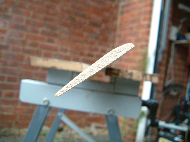
This is the part of blade construction that involves a bit of planing and a lot of checking to see if thing look right. It is best to do all the blades at the same time to get them as close to the same shape as possible. Here is a shot of a blade-tip showing the aerofoil.
Cutting the Blade Ends
The hub-ends of the blades need to be cut so they will fit together and then be fastened to a hub for extra strength. I considered various options here as the centre of gravity of the blades is not exactly through the centre of the blade (mainly because a large amount of wood has been removed from one side). The true centre-of gravity can be found easily enough by balancing them on a steel rule. So it should be possible to cut the ends of the blades so they have a tip that lies directly on the centre of gravity.
Call me a coward. I had spent many hours chiselling and planing these blades, and I thought if I screw-up here, I need to throw them away. So I opted for the simple solution of just cutting the blades to a point in the physical centre. Perhaps this will have implications, I don't know until I try but I reasoned that if this is an issue, I can always recut them and make the blades shorter if necessary. I keep coming back to the thought I have had some old drain-pipes turning the turbine so all these design considerations are maybe over the top for the first incarnation.
Having decided how the blades were to be cut, I made up some pieces of cardboard and cut them to the right angle (60 degrees or 30 degrees depending which face you measure from) to see that I was not making a measurement error. I wanted to be sure things were right before taking a saw to the wooden blades!
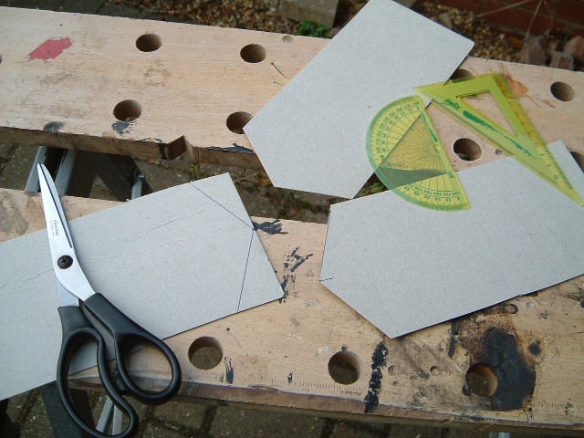
The cardboard fitted together as expected so I then used the same marking-out procedure on one wooden blades prior to cutting it.
I then used the first blade as a template for the others.
Making the Blade Hub
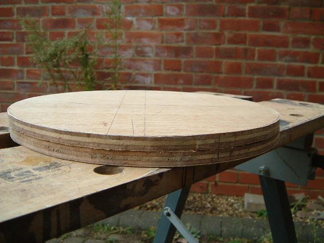
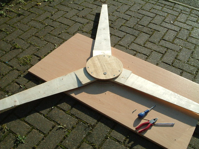
Well, after cutting the ends of the blades, I was pleased to say they fitted together pretty well and when I laid them out on the floor, they looked pretty much like a wind-turbine should do. In order to fasten them together securely, the plan was to sandwich them between two wooden discs like the design for the 12 Watt machine. As usual, over-engineering is not a bad option so I decided to make the hub quite large so there would be lots of anchorage points.
Rooting around, I found a large dinner plate was about the right size so drew around one of those and then cut two disks out of plywood. I found the centre of the disks and drilled a 3mm pilot hole which would be helpful for lining things up.
The next task was to actually assemble the blade and hub. Place the blades on a flat surface and then one hub was placed over the top. Push all the blade in towards the centre to get a snug fit. A 3mm drill pushed through the hole in the top hub passed through the join beyween the three blades. This ensures everything is lined up correctly.
With a tape-measure, measure the distance between the tips of all three blades and move them slightly so the distance between them is all the same, ensuring they are pushed into the center at all times. It only takes a very small shift of a few mm at the hub to move the tips by several cm. When all looks ok, drive a screw through the hub and into one of the blades. Remeasure and recheck. Repeat for the other two blades. If all looks ok, put an extra screw in per blade to fix them in position. At this stage, it will be possible to turn the blades over and repeat the process for the second disk. The whole assembly now starts to look more like a set of turbine blades.
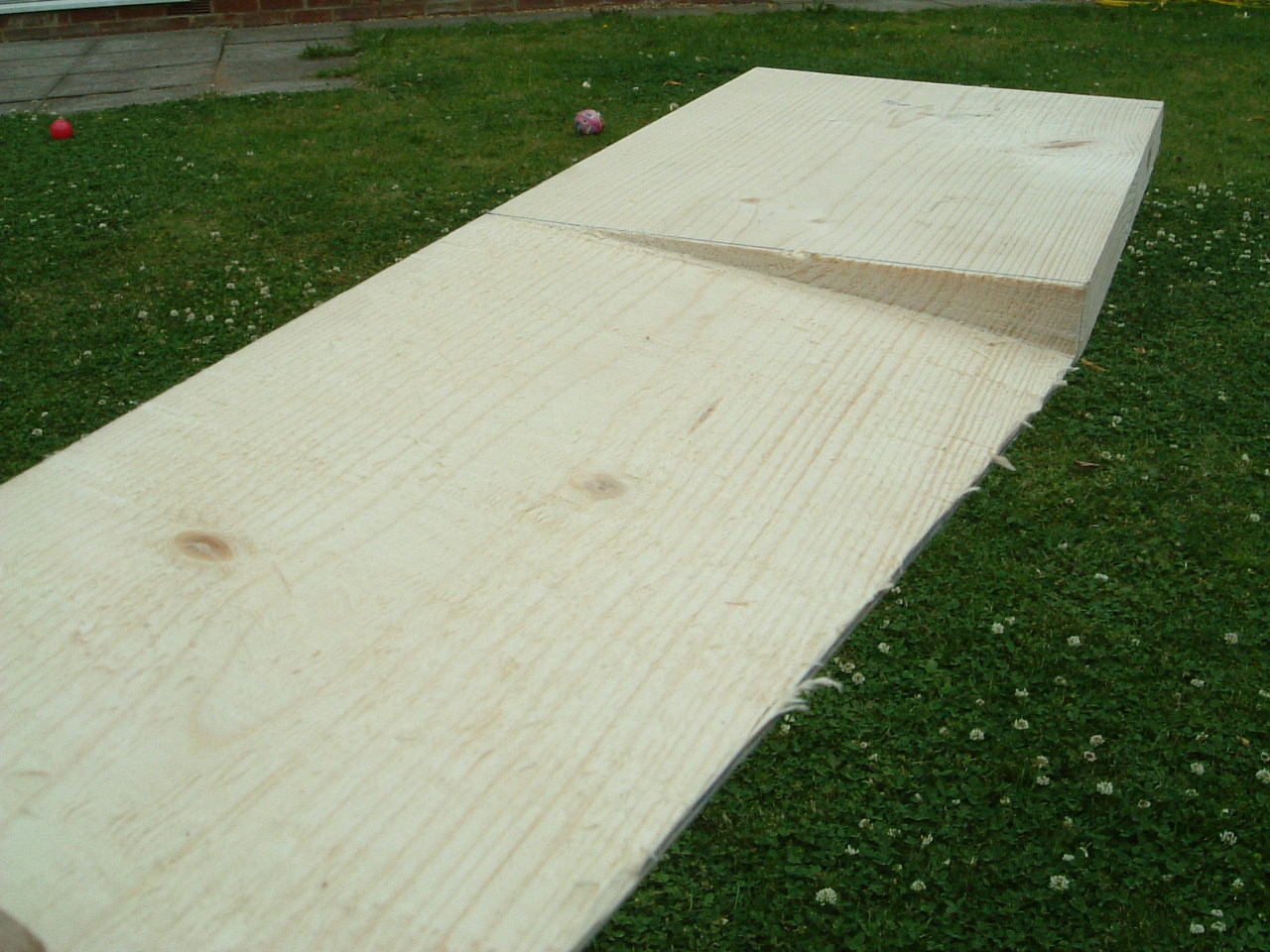
Once everything was aligned, screws were then driven through the hub into the blades from each side, totalling about 20 screws/blade so they should not move in a hurry. Once this was done, after marking up so that they would be assembled in the same order, the whole blade assembly was dismantled for weatherproofing. A couple of coats of wood preservative was used initially before painting 3 thick coats of outdoor gloss paint over the top once reassembled. I had used varnish on the previous set of wooden blades and although it may look nice, I don't think it has the same weatherproofing properties as paint does. I'm sure a good painted finish can be achiebved by sanding down and painting several thin coats but I just want the thing to be waterproof ! Here is a picture of the painted assembly:
| Home | Contents | Start | Prev | 1 | 2 | 3 | 4 | 5 | 6 | 7 | 8 | 9 | 10 | 11 | Next |