| Home | Contents | Start | Prev | 1 | 2 | 3 | 4 | 5 | 6 | 7 | 8 | 9 | 10 | 11 | Next |
Power Distribution
Power Distribution
Up until now I have been concentrating on generating and storing power. There is still much to do in this respect, more batteries need installing and I need to build a box to hold the battery bank, preferably outside, to avoid the buildup of vapour that arises from the charging process. For now, I have 120Ah of battery which is a good place to start. I suspect that you actually need in excess of 500Ah to be really useful. However, I will cross that bridge later.
Currently I am not making use of the electricity I am storing and this is mainly due to not having a means to easily distribute it. I have a 300 Watt inverter which is useful for running small power tools, lights and radios in the garage, but up until now, it has been a fairly ad-hoc arrangement and I need something more permanent.
It is less efficient to convert 12 Volts to 240 Volts just to transform it down again. I decided that a distribution system needs to have a High Voltage (HV) and Low Voltage (LV) output so I can drive 12 volt DC appliances directly (or even convert them down to lower voltages). I intend to do some experimentation with low-voltage lighting at some stage rather than using 240 Volt bulbs.
A 300 Watt inverter will draw 300/12 = 25 Amps at maximum working load. The rated capacity of the wire I have at hand is rated at 50 Amps so it seemed a realistic goal to set a maximum output of 600Watts (50Amps) which means 25 amps to feed the inverter and 25 Amps for the low voltage circuit. This gives a degree of flexibility as I can trade LV off against HV provided I do not exceed 600 Watts. Incidentally, drawing 50 Amps from my existing batteries will flatten them in a a couple of hours so 600 Watts seems a good maximum for the current setup. Larger batteries may mean I can crank things up in future but I feel 600 Watts is ample.
Distribution Panel
I built the distribution panel using the leftover wood from blade construction and boxed it so I could rest the regulator on top of it. It is a very simple affair and is shown in the picture below. In this case it is powering a 60W lamp via the inverter so is drawing 60/12 = 5 A current. (The inverter is about 90% efficient.
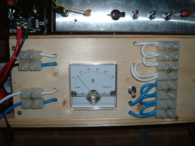
The main 12V dc feed from the battery comes in at the bottom left of the panel. It passes through the meter and onto the strip of 12 volt connectors at the right of the panel (4 outputs). The output from the meter also goes through a switch which routes voltage to the connector at the top left of the panel. This is used to feed the inverter so the switch can be used to to turn HV (240v AC) power off.
I need to consider what type of connector to use to connect 12volt appliances to the LV ring. THe only 'standard' 12V connector I am aware of is a cigarette lighter socket as used in a car. Not only are these aweful, they have a limited maximum useful power rating although having a few such sockets to plug in car-accessories wont go amiss. Whatever the solution, it must never be possible to plug 12V appliances into mains or vice-versa.
No fusing is done on the distribution panel, that is down either upstream or downstream nearer to the appliance using the current.
| Home | Contents | Start | Prev | 1 | 2 | 3 | 4 | 5 | 6 | 7 | 8 | 9 | 10 | 11 | Next |