| Home | Contents | Start | Prev | 1 | 2 | 3 | 4 | 5 | 6 | 7 | 8 | 9 | 10 | 11 | Next |
Mounting the Stator
 |
Stator Mounting
The 12 Watt design used the wooden disk that was left over from making the mold as the stator mounting bracket. I could easily have done the same with the 200 watt design but I was keen to use as little wood as possible. The solution was to use two 3mm thick upright steel strips welded onto the frame onto which the stator could be mounted.
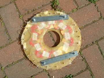
It is important that the stator is mounted in the right place, it must be central around the rotatable shaft so it is necessary to line up all mounting holes and to mount the stator brackets in the right place. First, I cut two 90mm strips of steel. The steel is 3mm thick so will easily hold the stator weight and not bend in the wind. I placed the strips on the stator to find a suitable place to mark 4 mounting holes. Due to the uneven distrubtion of resin on one side of the stator, I had to pick my spots carefully rather than blindly place them symetrically. The stator was marked and 4 6mm holes were drilled. The metal strips were clamped over the holes and those drilled as well so everything lined up.
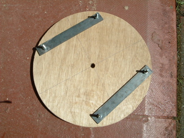
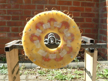
The wooden disk left over from the mold proved the perfect solution to mounting the stator brackets correctly. The centre of the wooden disk was drilled out with a 12mm hole (the shaft diameter). The wooden disk was then placed over the stator and lined up around the edges and then clamped together. The disk was drilled through the holes in the stator and the unclamped from the stator. The stator brackets were them bolted through the wooden disk, through the holes just drilled as shown below:
Now it was time to revist the frame. The wooden disk was threaded onto the shaft and then pushed back against the back of the frame and clamped in position, so the metal brackets were upright. We know they are correctly aligned with respect to the shaft as the wooden disk ensures this.
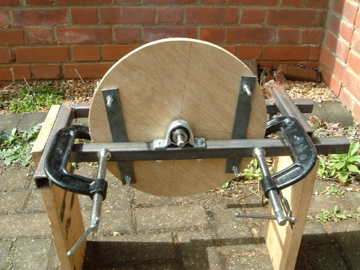
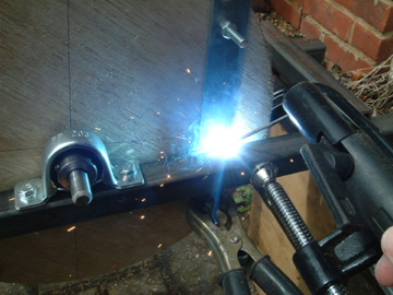
Now the brackets were welded into place. Initially with tack welds. The stator was mounted to check all was ok, then the welding was finished off.
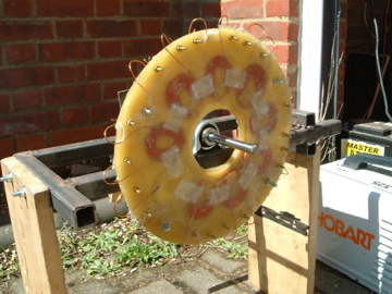
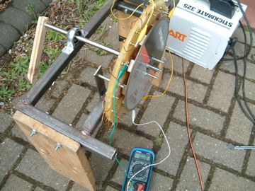
Now seemed a good opportunity to test the type of voltage that the stator could generate. To achive this, the stator was mounted on the back of the frame and the sprocket bolted on the back of on of the rotors. Obviously, this is not how the final design will be assembled but the frame makes a good test jig now :-). Turning the rotor at 120rpm gave a voltage across one coil of 1v (rms). This coil was wired in series with two more (every third coil counting around the stator) and repeating the test gave 3V rms across one phase. This is slightly less than I had estimated but (I had expected about 3.6V) but was definately in the right area. I had found from the 12 Watt design that adding a second rotor does indeed double the voltage generated. Therefore with this arangement, I can estimate:
At 120 rpm (one rotor):

Voltage per phase = 3v

So for two rotors, voltage per phase = 6v (rms).

If wired in Star, voltage between phases = 6 x 1.732 = 10.4 V (rms).

Peak voltage = 10.4 x 1.414 = 14.7 V (peak)

This will give 14.7 - 1.4 (two diode drops in rectifier) = 13.3V dc.
I believe in practice, the voltage dropped across the rectifier will be closer to 2V which will mean a 12.7 V output which means that charge cutin is going to occur at about 120 rpm.
I will test this all in detail as the machine starts to be assembled but from these initial tests, I can see that the 200Watt design wi start to produce charge at about 120 rpm whereas the 12Watt design does not do so until 220rpm. Provided that the blades have enough torque to get things turning, this makes sense as the larger blades mean the turbine will not rotate as quickly anyway.
Simple voltage testing:
| Home | Contents | Start | Prev | 1 | 2 | 3 | 4 | 5 | 6 | 7 | 8 | 9 | 10 | 11 | Next |