| Home | Contents | Start | Prev | 1 | 2 | 3 | 4 | 5 | 6 | 7 | 8 | 9 | 10 | 11 | Next |
Building the rotors
 |
Rotor Design and Construction
The rotors were made from 230mm angle-grinding discs (diamond-grit tile/maisonary blades). I obtained a large sprocket that had a 12mm bore that would be suitable for mounting the discs. When dealing with large discs and large magnets, several other factors need to be taken into account, namely:
- The two disks should be 'locked' together rather than just relying on their attachment to the shaft.
- There will be a very large magnetic attraction between the discs so a strong means of keeping them apart so they don't fall into the stator is required.
- Due to the strong attraction of the two discs, a safe means of assembling and disassembling the rotors is required
This last factor should not be underestimated. It would be a nightmare to put the two disks on the shaft, they slam down on the stator and then it is impossible to prise them apart. No kidding, these magnets are strong, it takes all the strength in my fingers just to prise two magnets apart. I would assume you could lose fingers if they got in the way of 24 magnets slamming together, so care and preparation are the order of the day
Rotor Spacing
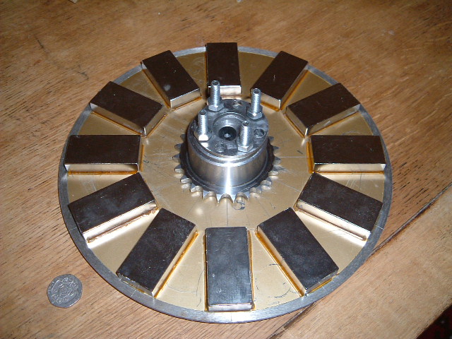
As for keeping the rotors apart, this required a bit of thought. On the 12 Watt machine I used a simple wooden spacer but I don't think wood is up to the job here. In the end I decided to choose a suitably large sprocket and use the sprocket itself as the spacer by mounting the magnets on the reverse side of the disk. This can be seen in the picture at the top of this page.
The magnets are 10mm thick. The stator will be 12mm thick. I'm going for a 2mm clearance between the magnets and the stator. This means the total distance between discs must be:
	10mm + 10mm (magnets) + 2mm + 2mm (clearance) + 12mm (stator thickness)
	= 36mm
The sprocket I obtained was 28mm thick. So I padded this with two 4mm thick 7/8 inch washers to give a total of 28mm + 4mm + 4mm = 36mm (surprise, surprise). I also got my hands on some thinner 2mm washers so I reasoned I could pad out the distance between the rotors to get it just right if necessary. Rather than using spacer washers, it may turn out better to just bolt the sprocket onto one rotor, and use the nuts as thick spacers. I'll need to experiment when assembling the alternator.
The two rotors will then be bolted together using 6mm bolts/allthread via holes drilled through the collar of the sprocket. At this stage it is worth considering how the two rotors will be separated if required once they have been assembled. One is to drill 4 extra holes through the sprocket and cut 6mm threads on them. This will enable 'jacking-bolts' to be threaded through from one rotor that will push the other rotor out when they are turned. An easier option is to just thread holes in the second rotor and use jacking bolts to pull it off the sprocket. I'm a little concerned that there is insufficient thickness in the rotor to achieve this. Just in case, I drilled and tapped the sprocket and will do the same on the rotor so if the second approach does not work, I can fall back to the second.
Once the rotors were completed, they were hung out of harms way, and separate from each other. I don't want the two rotors slamming together and not being able to separate them even before I try assembling the machine!
| Home | Contents | Start | Prev | 1 | 2 | 3 | 4 | 5 | 6 | 7 | 8 | 9 | 10 | 11 | Next |