| Home | Contents | Start | Prev | 1 | 2 | 3 | 4 | 5 | 6 | 7 | 8 | 9 | 10 | 11 | 12 | 13 | 14 | 15 | 16 | 17 | 18 | 19 | 20 | 21 | 22 | 23 | 24 | 25 | 26 | Next |
Heart and Brain Transplants
Gutting Mo
Shielding
I was very conscious about radio and electromagnetic interference when building Mo as I had been plagued with this with Lawna. It was also important as Mo had a radio receiver on-board. My solution to potential problems was to build every component in a screened metal box and use shielded cables to connect them. This may or may not have helped, all I can say is that I suffered no interference problems whatsoever but this approach is very labour intensive.
In an effort to move forward quickly, I plan to dispense with these precautions and just layout the components and connect them with standard wires. This suits a prototyping system better but I may find it necessary to resort to screening if things start behaving oddly.
Changes
Firstly, all the screened boxes were removed, along with their associated cabling. The locomotion motors were upgraded to something considerably more beefy. The same goes for the H-bridge driver. Simple screw block-connectors are used to connect sensors and I envisage needing a lot of these going forward. Electronic boards are mounted on thin ply that can be installed and removed quickly. Connections to the controller will be via header cables although I might need to replace this with a soldered proto-board if the connections vibrate loose.
The only part of the mower that remains unchanged is the grass cutting mechanism and motors. Since I will be concerned mainly with navigation, these don't need much attention as they worked pretty well previously. I will keep them in place to see the power consumption of the mower and it will be useful to see where the mower has been.
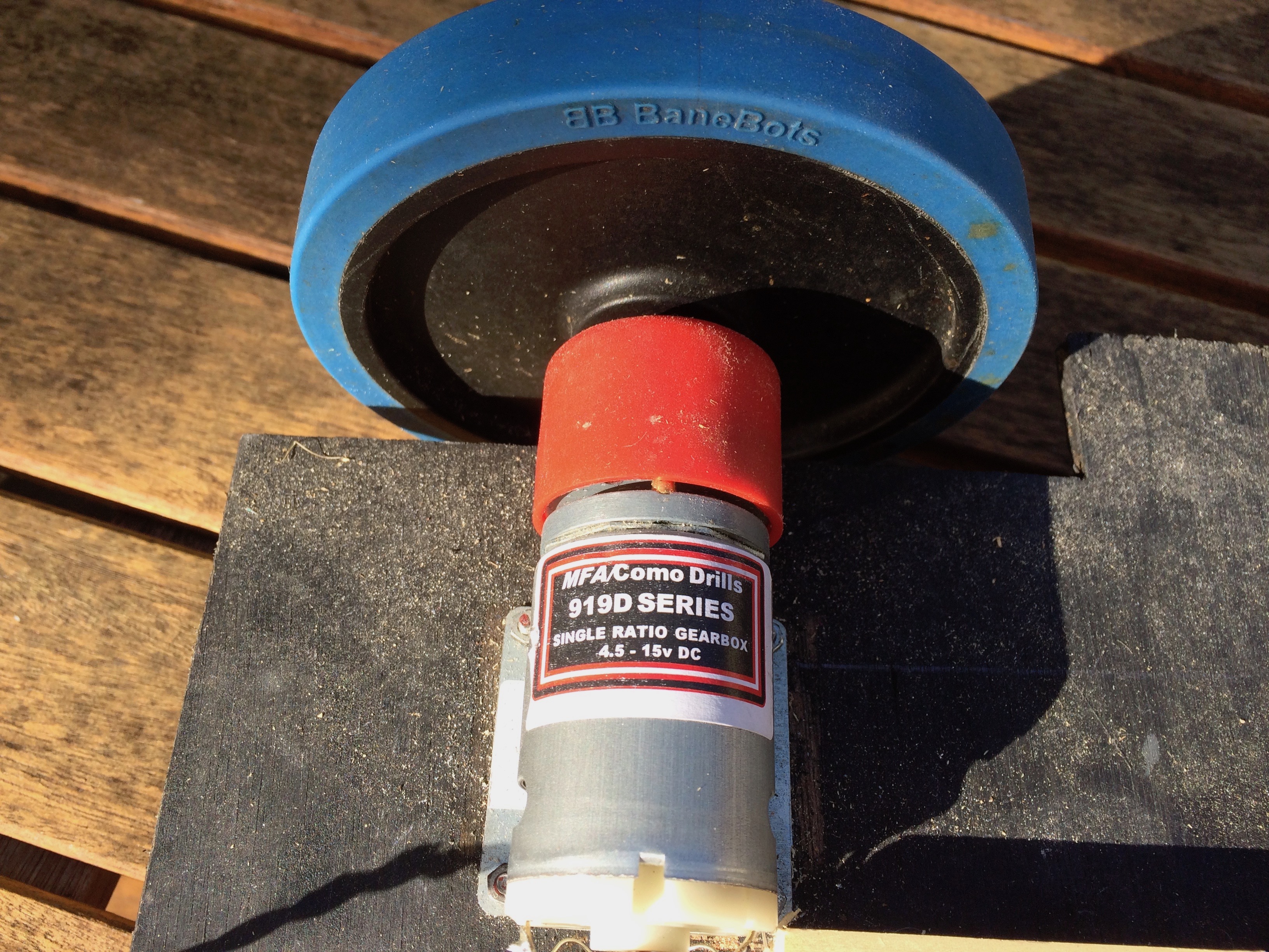
Locomotion Motors
These were the motors used which are a considerable upgrade to previously. They have a 500:1 gearbox and considerable torque. Locomotion Motors.
919D5001 RE 540/1 Metal Geared Motor 500:1
Output @ 12V 30rpm 77200g/cm at max efficiency, stall torque 500000g/cm
21 Watts => approx 2A per motor, probably be less on the flat.
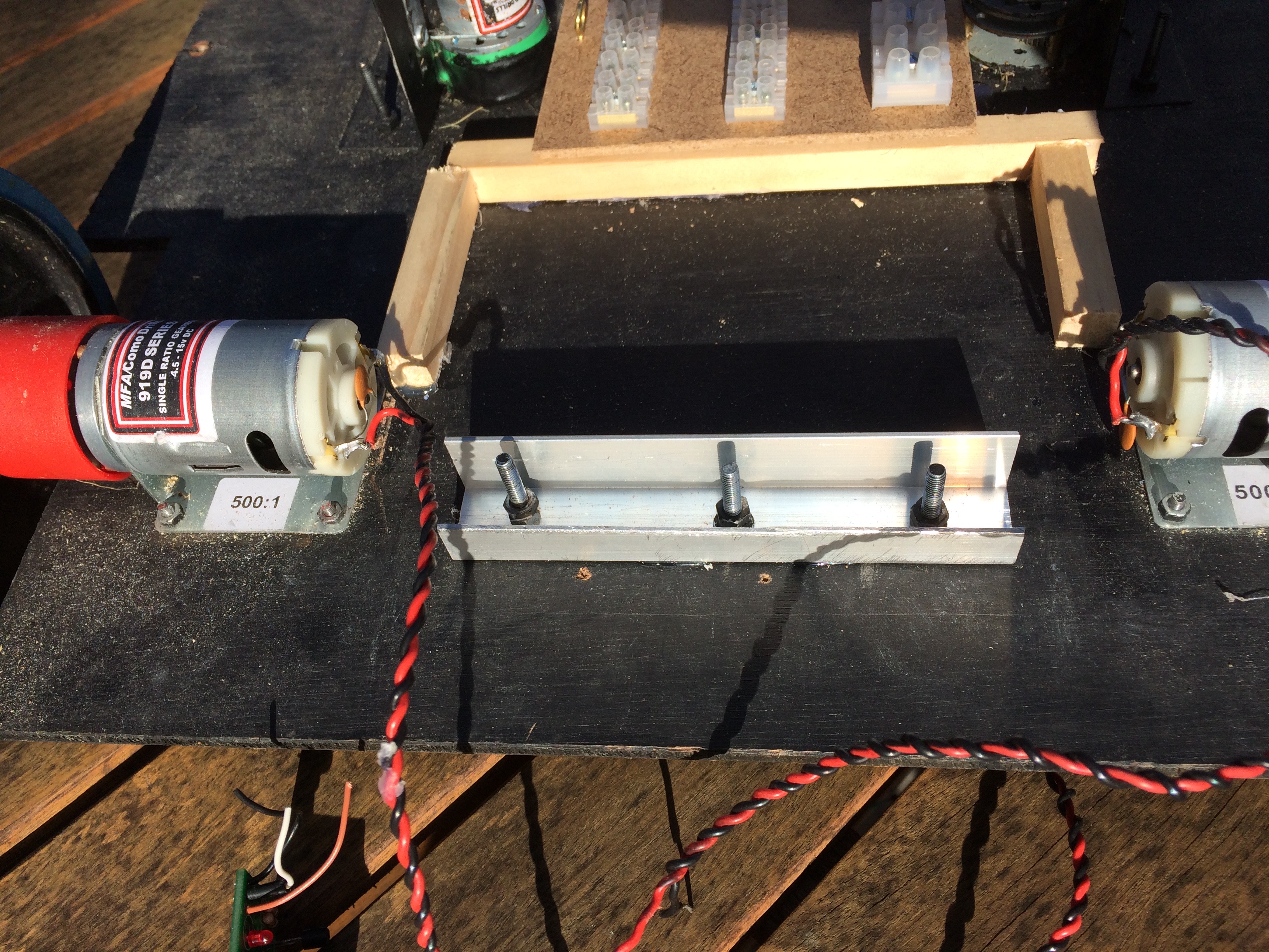
Battery Bracket
Here is the upgraded battery support mount. With more powerful motors, the mower will be able to tackle steeper slopes so the battery mount was upgraded to use a bolted aluminium back-frame to prevent the battery falling off the back of the mower.
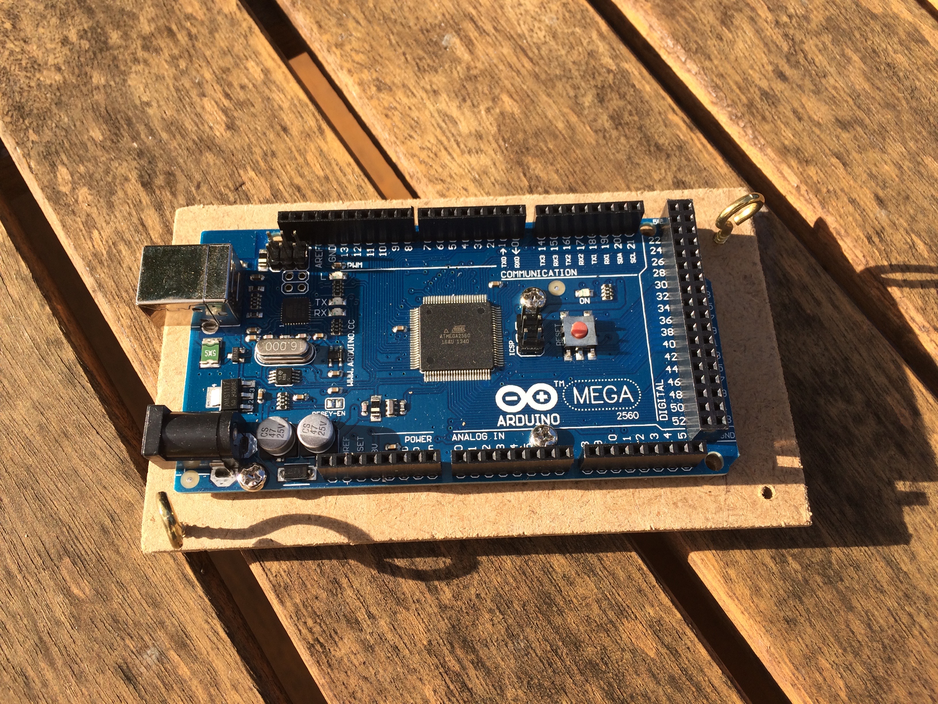
Microcontroller
The microcontroller was upgraded from a UNO to a Arduino Mega2560. It is mounted on a thin ply board that can be easily removed from the mower for testing. It is mounted with two (or more if needed) thumbscrews.
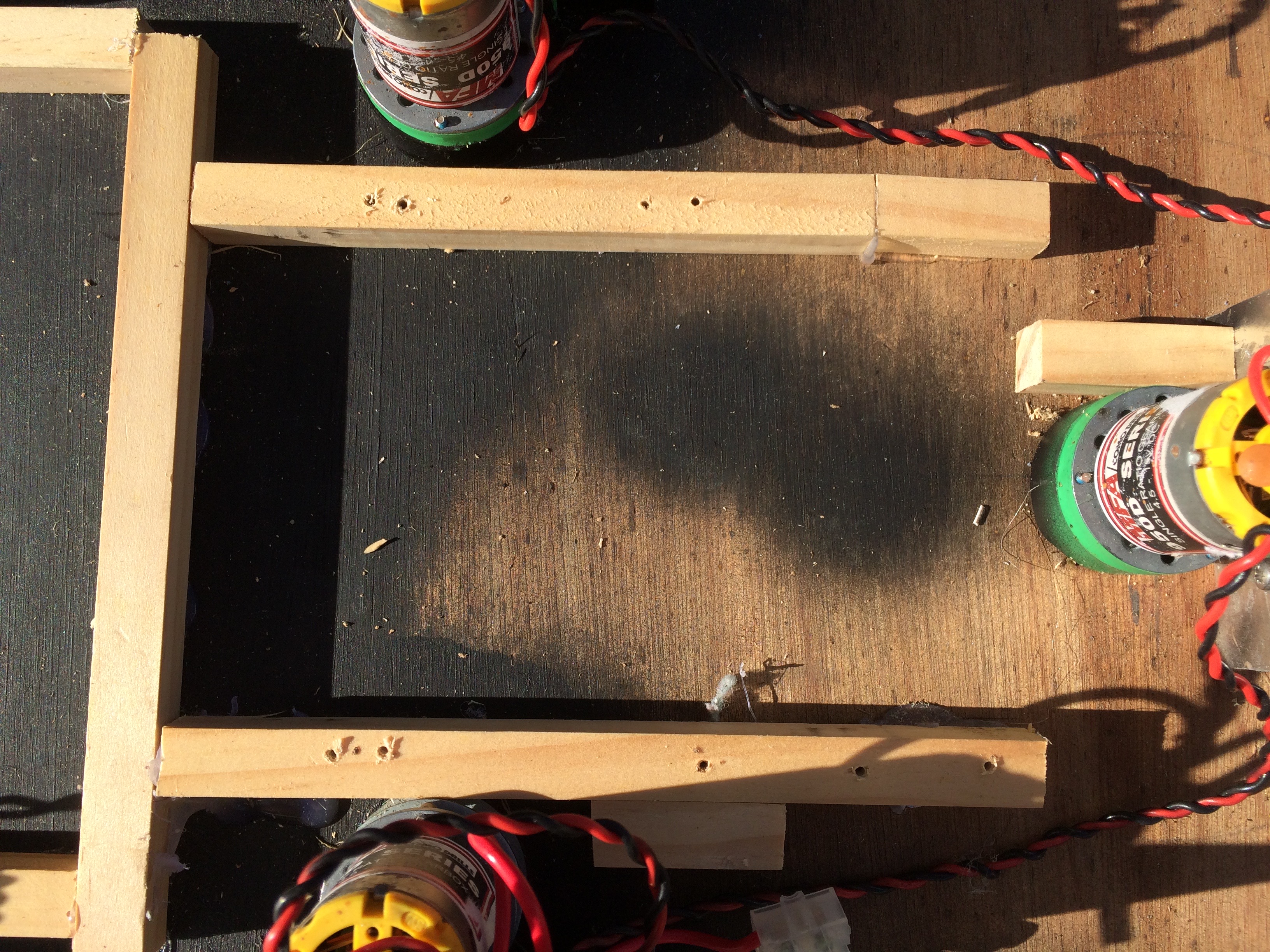
Mounting Rails
Wooden rails glued to the chassis form the mounts that the ply boards are attached to via thumbscrews.These were salvaged from Mo where they were used to hold the metal enclosures in place.
Power Distribution
Another board was made up with a Pololu 5V, 5A Step-Down Voltage Regulator D24V50F5 as well as a Pololu 3.3v 2.5A regulator. I left lots of connectors free on the board so there was a common ground strip, a common 5V strip, a common 3.3V strip as well as a smaller 12V distribution strip. This hopefully will prove useful for connecting sensors. I'm still not decided on powering the arduino, as there are various options but it would be good to isolate it from the noisy 12 supply.
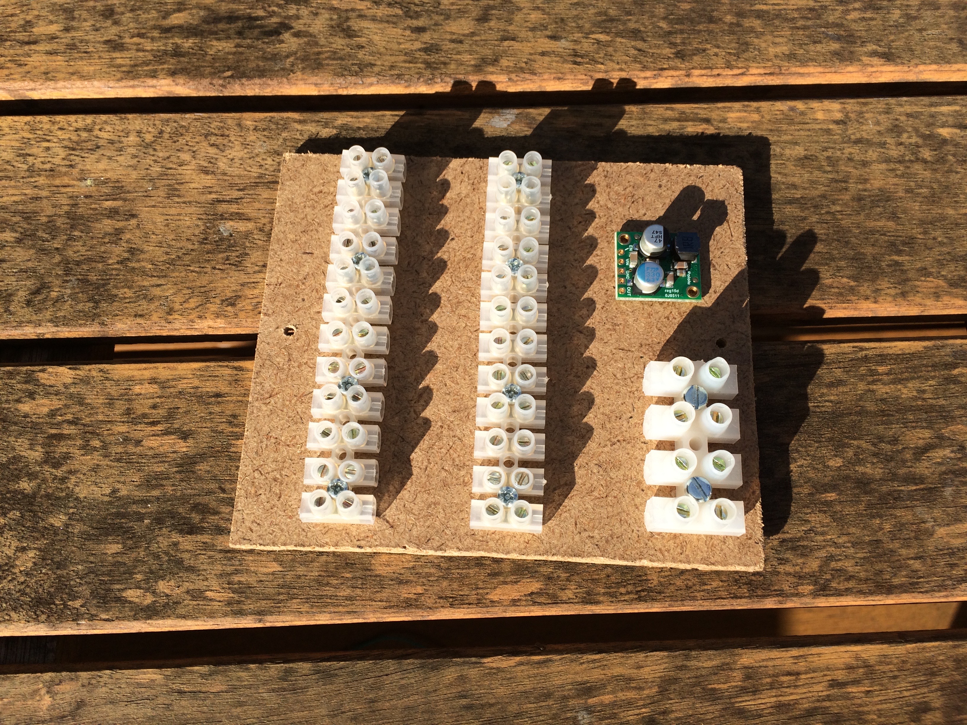
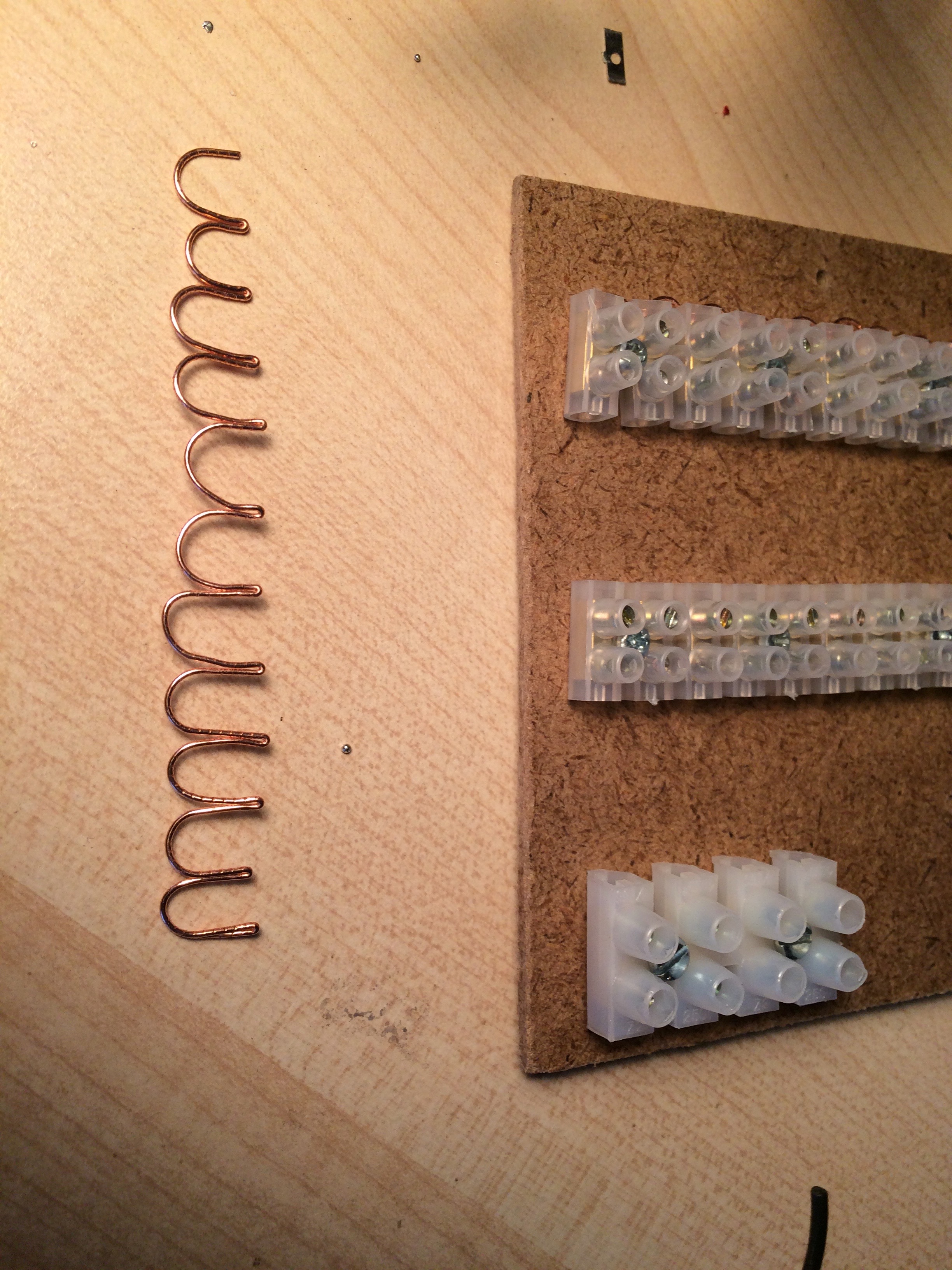
The power strips were made by using a strip of thick copper wire to run the length of the connector blocks. Note that it is only connected at one end to prevent earth-loops (same for the 5v/3.3v strips).
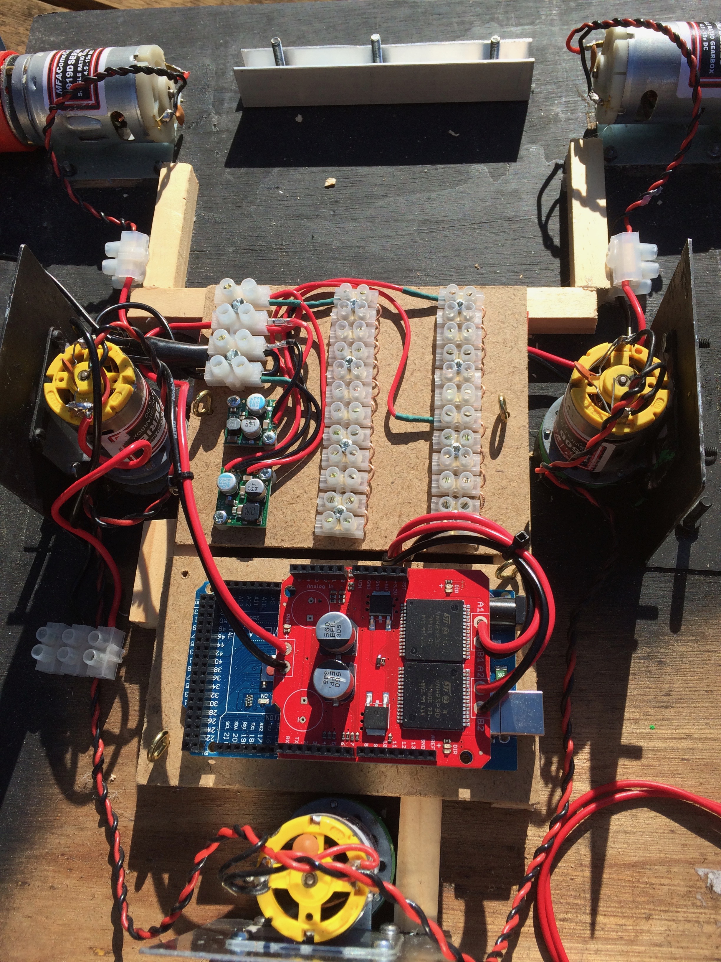
Mounting the Boards
This image shows the power distribution board and the Arduino Mega mounted on the rails. This system works well as the boards can be removed very quickly.
H Bridge
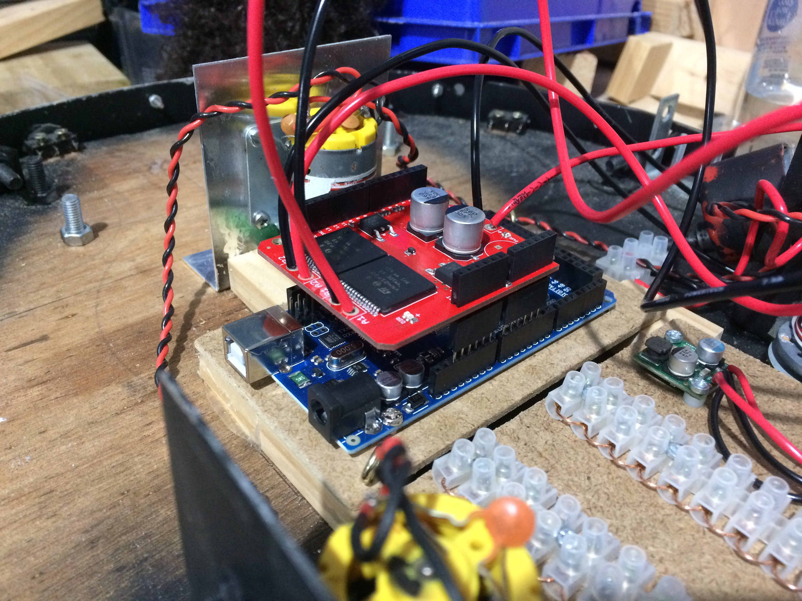
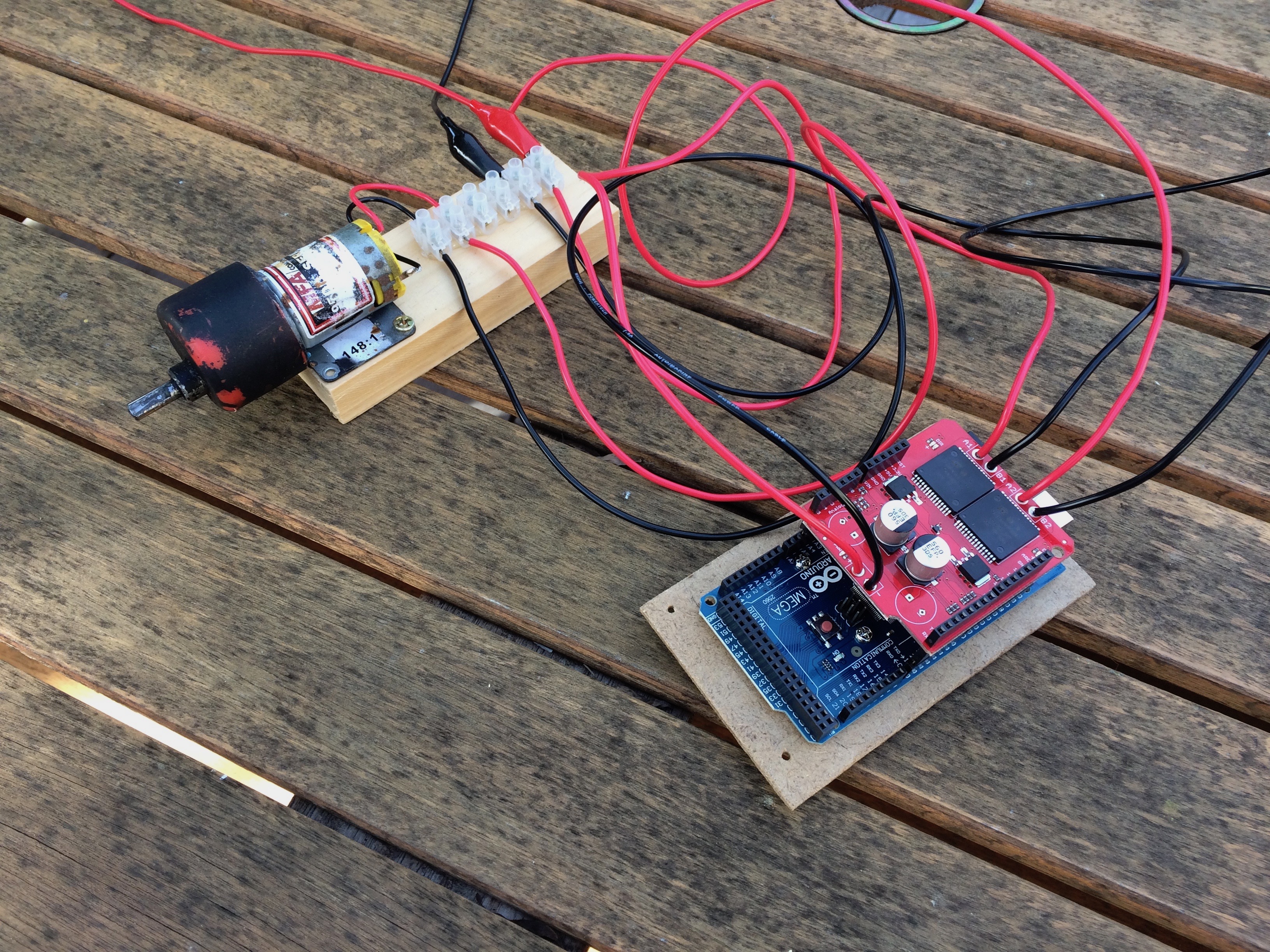
I upgraded the H Bridge to use the Sparkfun Monster Motor Shield. This is bit of a beast and is not cheap but should provide ample current should I need it (6A with no heatsink) and capable of peak current up to 30A. I hopefully wont need to go there but having plenty of headroom is good, especially as the device has over-current and temperature shutdown, as well as a way of monitoring the current used. The dimensions of this board were such that when plugged into the Mega, it was very close to shorting the bottom of the board to the Mega USB Connector. To give some headroom (and better air circulation), I used an extra set of arduino headers to raise it higher above the arduino. See the picture below.
I used one of the old locomotion motors to test the H-Bridge while developing the motor driver APIs.
March 2018
| Home | Contents | Start | Prev | 1 | 2 | 3 | 4 | 5 | 6 | 7 | 8 | 9 | 10 | 11 | 12 | 13 | 14 | 15 | 16 | 17 | 18 | 19 | 20 | 21 | 22 | 23 | 24 | 25 | 26 | Next |