| Home | Contents | Start | Prev | 1 | 2 | 3 | 4 | 5 | 6 | 7 | 8 | 9 | 10 | 11 | 12 | 13 | 14 | 15 | 16 | 17 | 18 | 19 | 20 | 21 | 22 | 23 | 24 | 25 | 26 | Next |
Trial by Compass!
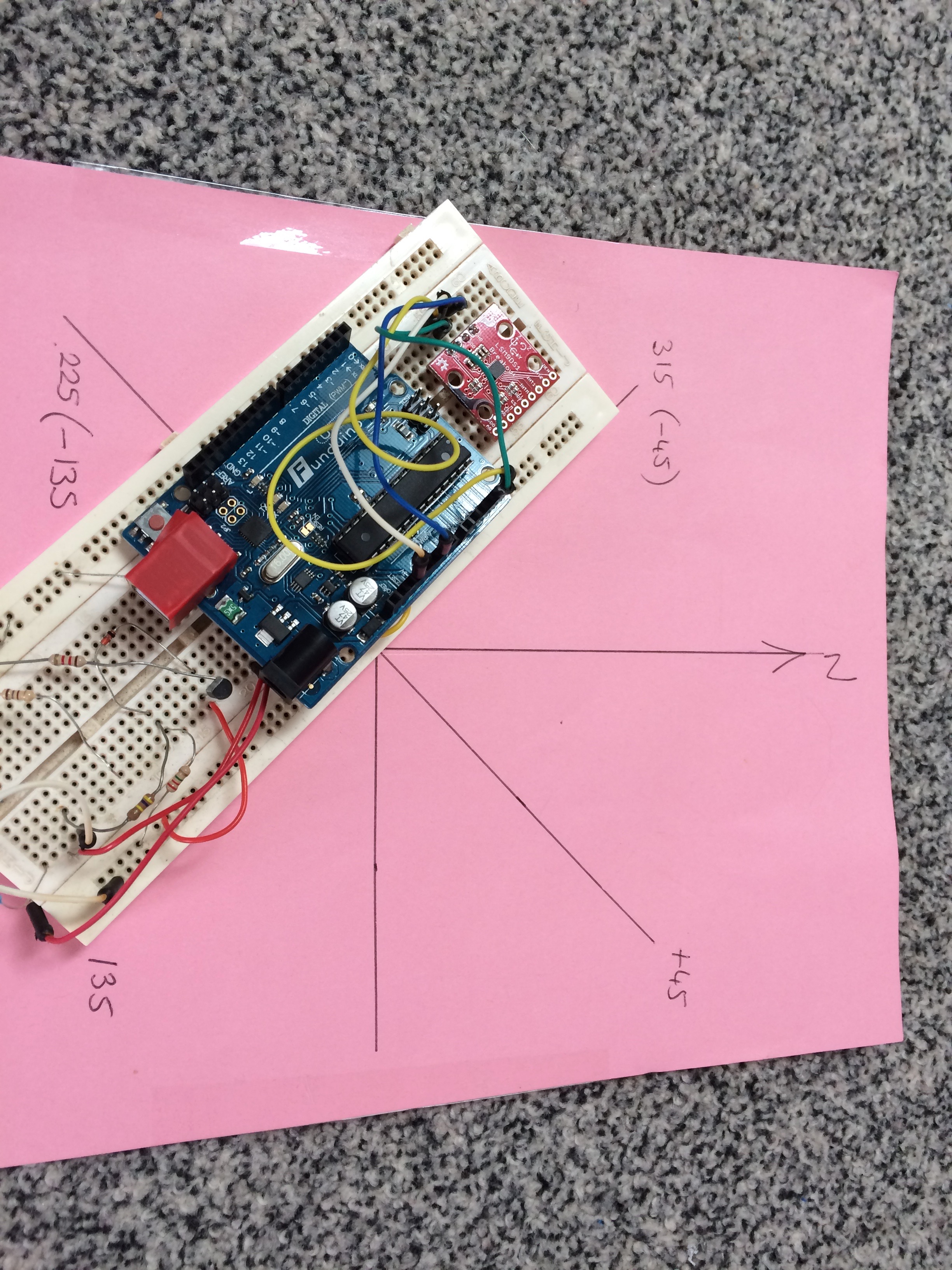
Well, this proved to be rather more challenging than I envisioned! Although connecting up the compass and getting a bearing from it was very straight-forward, the data I was getting was at least, confusing and at most, just erroneous. After mounting on the mower, in certain directions, it was possible to follow a bearing and then the mower would veer off in a random(ish) direction. At first I thought this was interference and I tried screening the cable, but to no effect.
Returning inside, I again tested the compass on a Uno and started mapping out the directions I was getting out of the compass. It was pants. Over certain angles it made sense, others it did not. I started doubting my sanity and dived into the Sparkfun library. I had doctored this to get a heading, using Sparkfun code. The function I am interested in is below.
void calculateHeading(float mx, float my)
{
  if (my == 0)
    heading = (mx < 0) ? PI : 0;
  else
    heading = atan2(mx, my);

  //  heading -= DECLINATION * PI / 180;

  if (heading > PI) heading -= (2 * PI);
  else if (heading < -PI) heading += (2 * PI);
  else if (heading < 0) heading += 2 * PI;

  // Convert everything from radians to degrees:
  heading *= 180.0 / PI;
}
This made sense to me and I worked through this for various angles and was happy it was correct. However, the raw output from the magnetomer is a voltage for each axis. The IMU has a function called calcMag() which returns a value in gauss which is positive or negative depending on the quadrant. This is what I needed for the atan2 function to work. This meant the call to calculateHeading() became:
	imu.readIMU();
	calculateHeading(imu.calcMag(imu.mx), imu.calcMag(imu.my));
The above helped, but was rather confusing, I seemed to be 90 degrees out. On reading the data sheet, I saw that the magnetometer was mounted 90 degrees out to the accelerometer so I switched the mx and my values in the call to calculateHeading():
	imu.readIMU();
	calculateHeading(imu.calcMag(imu.my), imu.calcMag(imu.mx));
Level Shifting
The compass is 3.3 volt device. Although I ran the compass from the 3.3v supply, I realized that the arduino probably has pullup resistors to 5v on the I^2C line SDA and SCL. This is unlikely to help matters and will possibly destroy the compass. As a quick workaround, I soldered two 4.7k resistors to these lines and pulled them up to to the 3.3v line. I may buy a dedicated level shifter as I may end up with with both 5v and 3.3v devices on the I^2C bus.
Calibration
Things started to make more sense now. I identified the correct way to mount the compass for my use but the readings were still inconsistent. I decided that maybe it was necessary to calibrate the compass, like you do with an iPhone app and started poking around in the Sparkfun library. And low and behold, there is is:
void LSM9DS1::calibrateMag(bool loadIn)
If loadIn is true, the calibration data is stored in the offsetMag registers of the device. So I hooked into this and added it to the setup() method in the arduino code and tried to rotate the compass carefully to calibrate it. You get about 3 seconds and this is difficult to do with a Uno and USB cable attached. I changed the for-loop limit from 128 to 1024 which gives about 15 seconds to calibrate.
Post calibration, the compass worked as expected giving an angle between 0 and 359 that correlated within about 15 degrees to my manual compass. This I can work with, so I was pleased with this result. Repeated trials gave fairly consistent results. Unfortunately, this was not the end of the story. If I power off the magnetomer and power up again, it seems to have lost its mind. Recalibrate and all is good so the writing of calibration data does not get preserved, the registers are memory based.
It would not be the end of the world to get the mower to calibrate on startup, it could do a simple pirouette before becoming ready to mow. However, I want the mower to be placed on the grass pointing in the direction to mow. On startup, this becomes the setpoint bearing which is use in the main code. Performing a pirouette would mean the bearing would not always be correct as it depends on the state of the ground where the mower ended up pointing. So I came up with an alternative solution:
I got the Sparkfun calibrateMag() method to print out the offset values it used just before writing them into the registers. I saved these and created a function to write them to the device registers using the Sparkfun code:
/*
 * this uses values calculated above during a calibration session. I don't want to recalibrate
 * each time as Mo is too heavy and don't want him to spin in circles. So we write these offsets
 * up-front.
 */
void writeMagOffsetRegisters() {
  //x,y,z
  int16_t mBiasRaw[3] = {1658, 1503, 2038};
  for (int i = 0; i < 3; i++) {
    imu.magOffset(i, mBiasRaw[i]);
  }
}
Now the main setup() method in the arduino code just calls writeMagOffsetRegisters() which writes those values on startup. Powering off and restarting sees the compass is sane again. With Uno tests complete and consistent, it was time to put the compass back onto Moana and see the results. I still think there is a place for the pirouette aut-calibrate and may add mechanism to do this that is triggered from a serial port command.
Running on a Bearing with a sane Compass
Now the compass was returning sane values, I could start to drive on a fixed bearing. Almost. The mower kept veering slightly left even thought the logs told me it was correcting for the compass bearing. I made sure the compass was aligned correctly with the mower. It was.
Perhaps the motors were slightly out when running at the same pwm values. I was pretty sure they were close as I had tested these when building up the main motor locomotion routines. So I took out the compass code and tried running in a straight line with both motors at 200 pwm values. Low and behold, the mower was veering badly off to the right. I adjusted the pwm settings and found there needed to a difference of 30 to get an approximate straight path. This seemed rather a large difference to me, I would have noticed this during earlier motor testing. So It was time to look at mechanics.
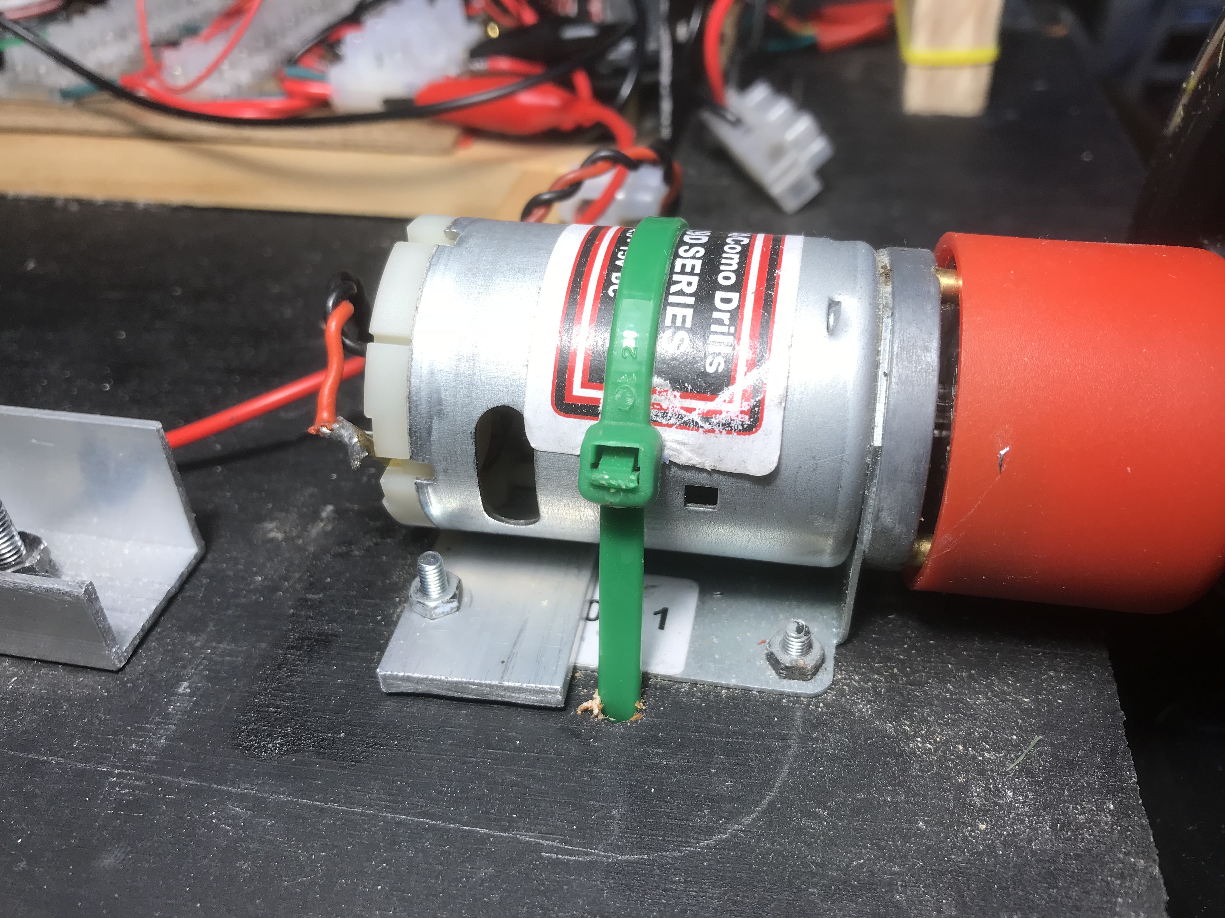
The wheels of both motors were attached securely. The motors were both attached to the chassis securely. On poking about, I saw the left motor could twist very slightly in its bracket whereas the right motor could not. These are the standard brackets that come with the motors, not much I can do there. I used an aluminium plate as support under each motor and jacked it down with a tie-wrap to make sure there was no movement. Running the motors again, using a pwm of 200 for each wheel and the mower went pretty straight. So a mechanical problem looks to be the root cause.
So, back to the compass. Once again, I launched the mower off on a bearing and this time it went where it should have, making minor adjustments if it went off course, both left or right. I'm using simple proportional control with a P value of 10.
The mower can now run in any direction and steer to that bearing. Pushing the mower deliberately off-course will result in it correcting itself to continue on original bearing. Time for a beer I think.
April 2018
| Home | Contents | Start | Prev | 1 | 2 | 3 | 4 | 5 | 6 | 7 | 8 | 9 | 10 | 11 | 12 | 13 | 14 | 15 | 16 | 17 | 18 | 19 | 20 | 21 | 22 | 23 | 24 | 25 | 26 | Next |