| Home | Contents | Start | Prev | 1 | 2 | 3 | 4 | 5 | 6 | 7 | 8 | 9 | 10 | 11 | 12 | 13 | 14 | 15 | 16 | 17 | 18 | 19 | 20 | 21 | 22 | 23 | 24 | 25 | 26 | Next |
Sonar Sensors
Adding a forward facing sonar was the first task. I want to add side facing sonars later so need to design the mechanics to cater for this in the future. I decided to make a small platform the width of the mower which would elevate the sensor about 10cm above the chassis to prevent false triggering in long grass or leaves.
HC-SR04 Sensors
The sonar modules used were HC-SR04 sensors. These seem to be poorer than the SRF05 sensors I have used previously but we will make do as it seems SRF05 sensors are hard to come by in New Zealand. The HC-SR04 appears to have a narrower beam width but I am using it on a larger robot and outdoors which is something I have not done before.
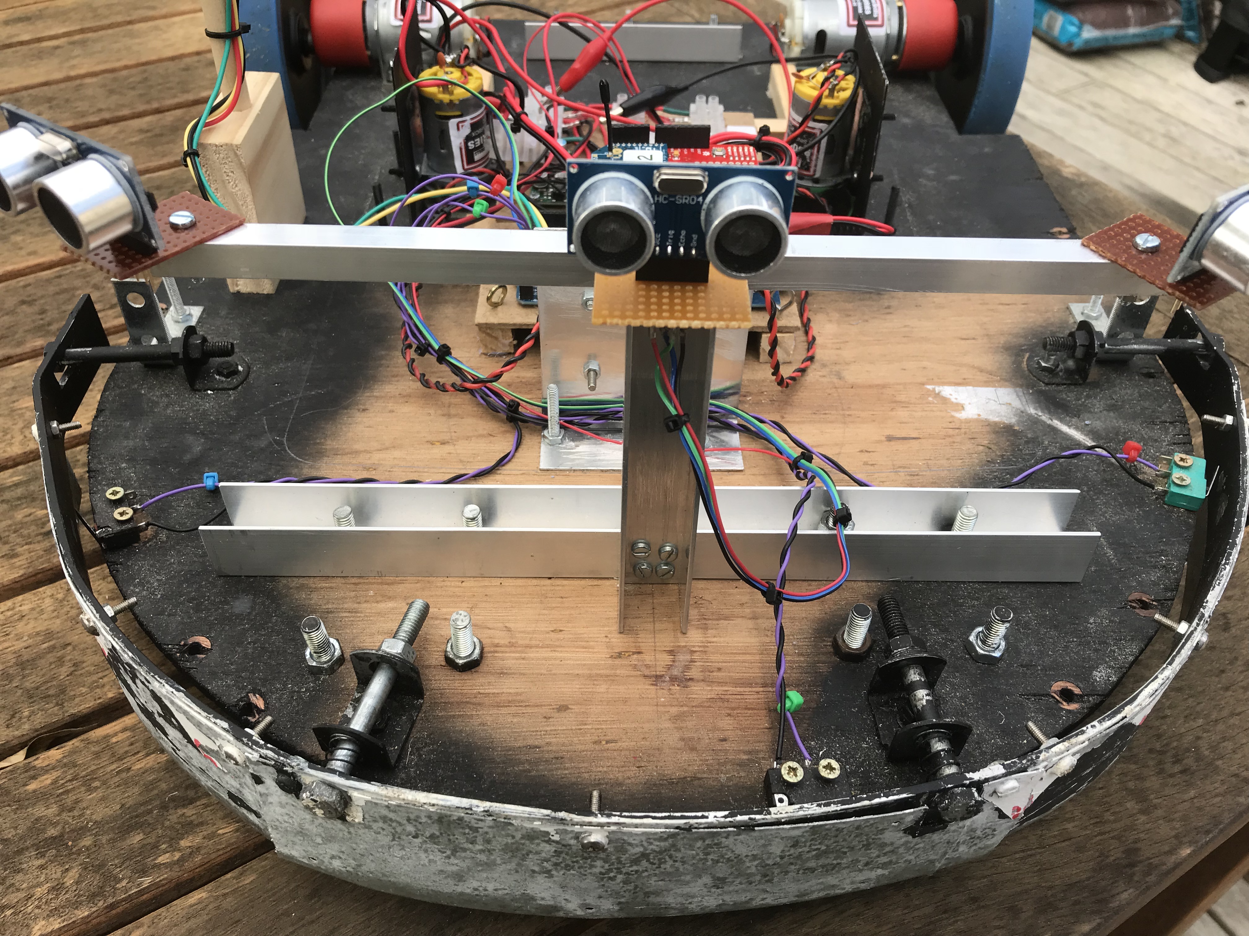
Aluminium channel was mounted to the chassis using the same bolts that hold the castors in place. A small aluminium tower was used to raise the sensor. The plan is to add two or more side sonars later, so the top of the tower has a smaller beam bolted to it, to allow for expansion later.
The sonar tower. I made this higher and wider than I think is necessary. After testing the beam coverage, I will probably shrink it down, but it is easier to trim it down later than to make it larger!
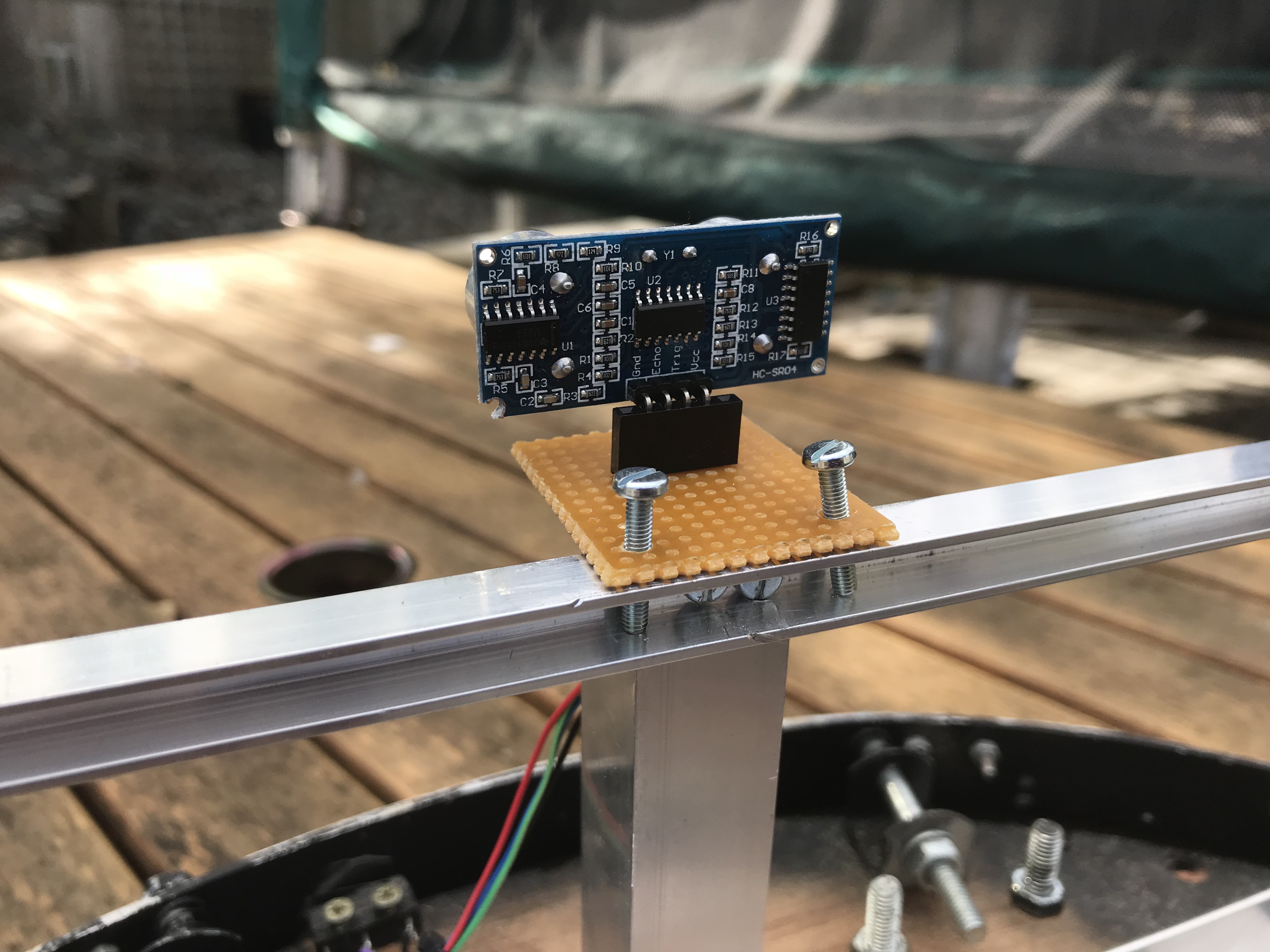
The sonar modules are mounted on small veroboards. I used an arduino header as the long pins are useful for attaching header wires. It also allows the module to be mounted/dismounted quickly during construction. Note the row of breaks in the copper to prevent the aluminium frame from shorting things out. When testing is complete, the modules will be soldered onto the board in front of the arduino connector.
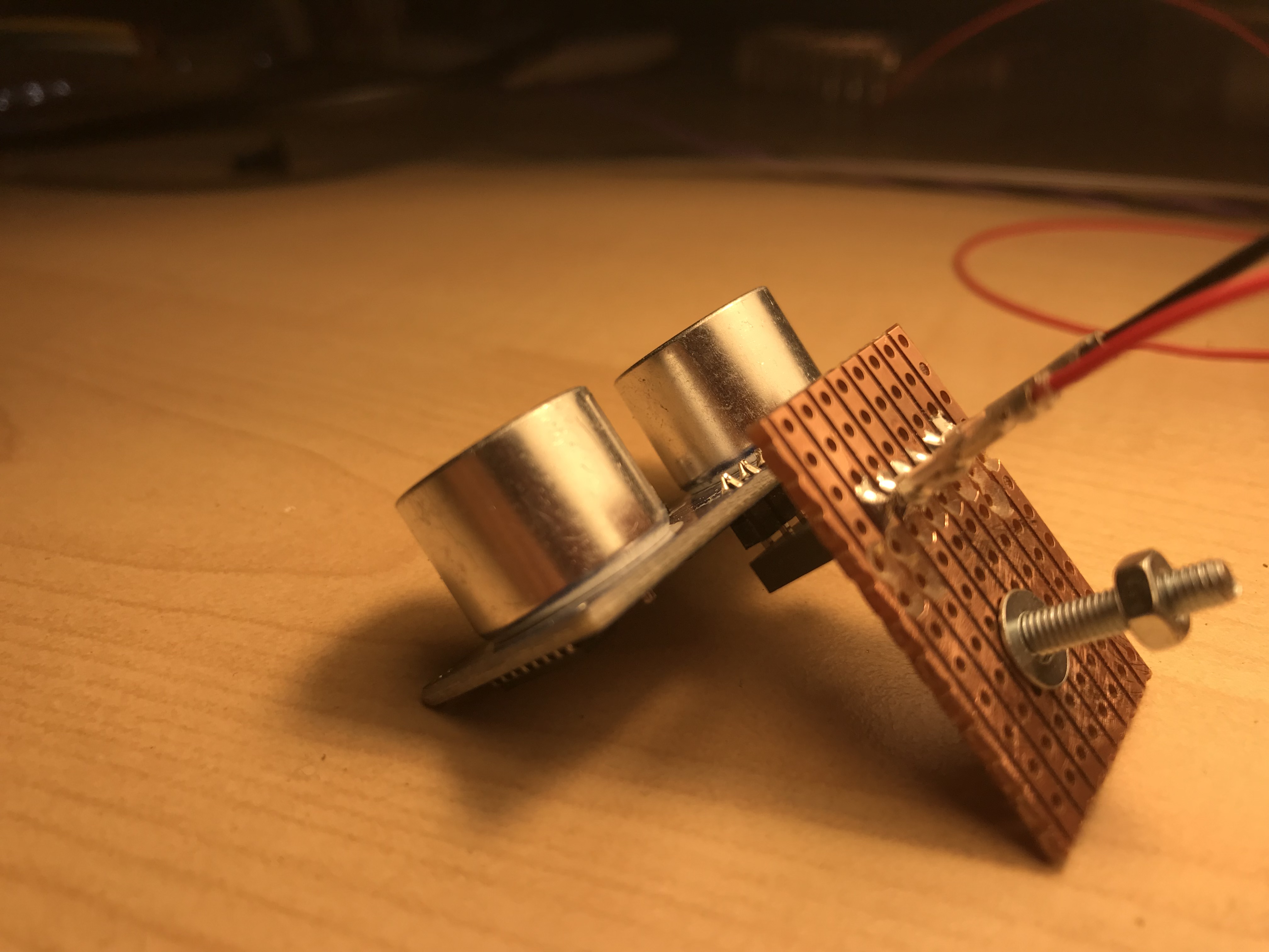
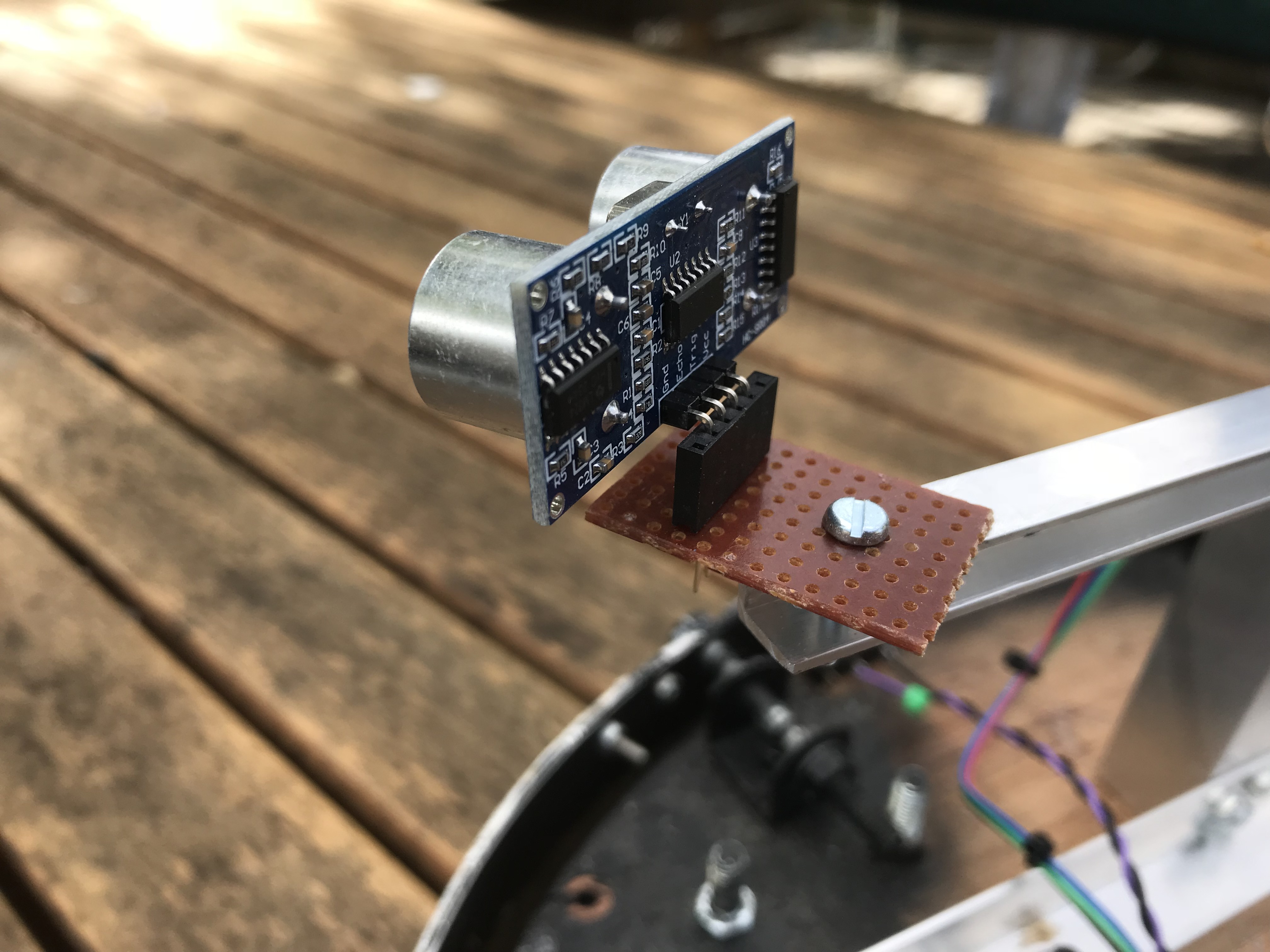
Here is the central sonar prior to mounting.
The side sonar mounts were similar except they only have one central mounting bolt. This is to allow them to be swivelled to cover more of the side or front of the mower. They will be clamped down after doing some beam width tests.
HC-SR04 Sonar Beam Width
Before finally committing to the placement and positioning of the sonars, I decided to get some practical measurements of the beam widths as the data that comes with the sensors is rather vague. These sensors appear to have a narrow beam width. Generally, this is a good thing, but for this application, I need a fairly broad beam width and I'm not interested in anything more than a metre or two in front of the mower. Short and fat will do nicely.
Without going into the gory details, there were the results of measuring the beam-width of the central sonar as measured at 1 metre. The datasheet mentions a 0.5 metre square target. This is not practical for Moana, it needs to be able to detect relatively small tree trunks and bushes. I used a 3cm diameter dowel (similar to New Zealand standard broom handle) and it could not detect it at all, even if directly in front of the sensor at various distances. I Measured the beam width and got these results:
HC-SR04 Beam width: 12 degrees
Now that is a revelation! Long and thin rather than short and fat, not exactly what I was hoping for. Admittedly, this was using a 10cm wide vertical plank as a target, but I consider that a practical target. This means I would need up to 5 sensors to cover the front of the mower which seems rather excessive.
Before going banzai with a hacksaw, I need to consider my options in order to get a wider beam width to make the sonar sensor a practical alternative to bump switches:
- User up to 5 sensors in horizontal configuration.
- Experiment with mounting the sensors vertically.
- Investigate different sensor options.
Using 5 sensors is possible, the ArduinoMega has plentiful i/o pins. However, this adds a lot of extra wiring and complexity. I may have to fire each sensor sequentially which will slow down the processor while waiting for echos.
Vertical placement may reduce complexity, at the cost of some mechanical modifications to the tower. I suspect that the beam width is conical so this may not help but I have not done any measurements in this orientation yet. What concerns me most however, is that these sensors could not detect a 3cm dowel placed in front of the mower. This was not a blind spot, just poor sensitivity. It may be that the sensor is just pants, or to be fair, not that well suited to my application.
I started looking at the Maxbotix sensor range. These have much more comprehensive data sheets and they provide a range of sensors that have various beam widths. They are also temperature compensated, self calibrating, have various interfaces and can be left in free-running mode if required. In short, they look (according to the specs), much better sensors. One wide-beam sensor should be capable of covering the front of the mower within 1 metre so I decided to test one before going further. I will give the MB1003 HRLV-MaxSonar-EZ0 Ultrasonic Range Finder a punt and do some tests.
Maxbotix MB1003 Sensor
The Maxbotix range of sensors is quite large and come with different ranges but most importantly, different beam widths. The EZ0 range have the widest beam-width and may be more susceptible to false triggering but a wide beam width is what I need. The only problem I envisage is that it has a minimum detection distance of 300mm (guaranteed). 300mm as it happens, is the distance needed by Moana to execute a turn without bumping into anything.
Maxbotix Sensor Mount
The Maxbotix sensor is smaller so I ended up flipping the mount which brought the sensor further inboard, 100mm from the front of the mower. This gives some leeway with minimum detection distance. Here is the setup:
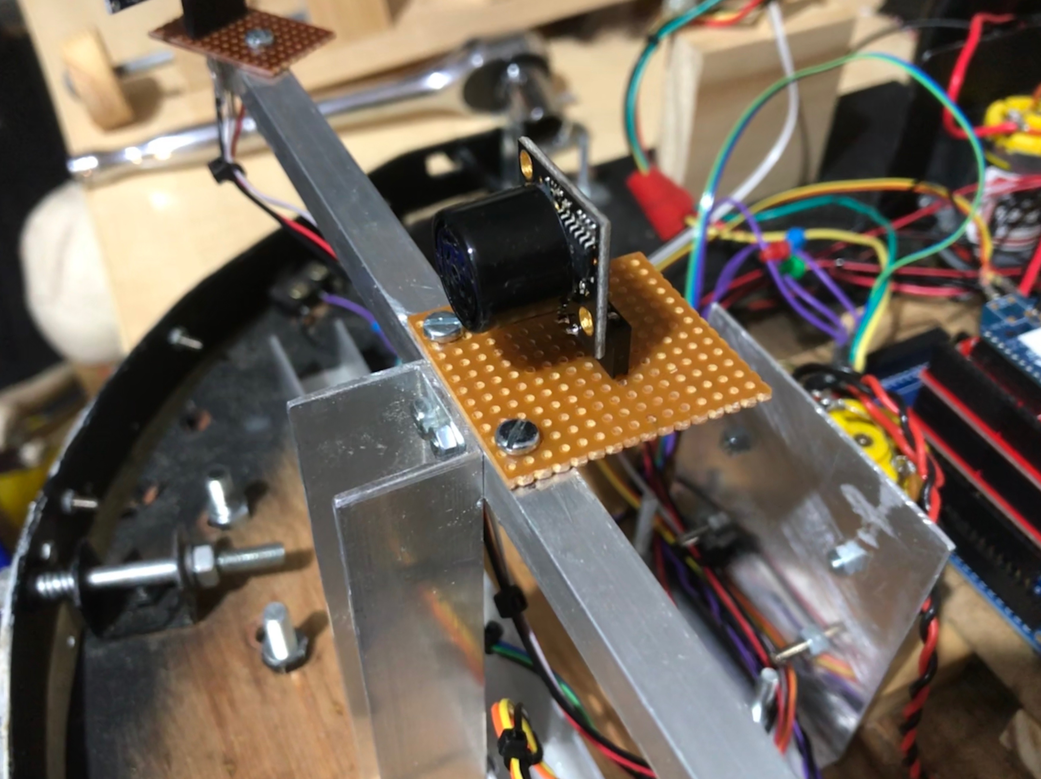
The sensor has a plethora of interfaces, perhaps the simplest to use is the analogue output but there is also a digital pulse width pin, similar to the HC-SR04 interface so I used that. This is neat device, here are some of its features:
- Multiple Interfaces to choose from.
- Temperature compensated.
- Self calibrating.
- PW Output is 1uS per mm so already in mm and does not require conversion.
- Freerun mode. i.e. it keeps pinging, freeing the arduino for other things.
- Can be used in trigger/echo mode if required.
- When in freerun mode, the pinger can be disabled.
MB1003 EZ0 Sonar Beam Width
I reran my my beam width tests. This is a totally different beast to the HC-SR04.
Firstly, the measurements it takes are highly accurate, much more accurate than I need (within 5mm). The beam width is much wider. At 300mm from the sensor (200mm from the front of the mower), the sensor can detect anything within the width of the front of the mower (440 mm). Even better, the sensor can easily detect the 3cm dowel at various distances so not only is the beam width better, the sensitivity is better. After some elementary maths, we can conclude:
MB1003 EZ0 Beam width: 60 degrees.
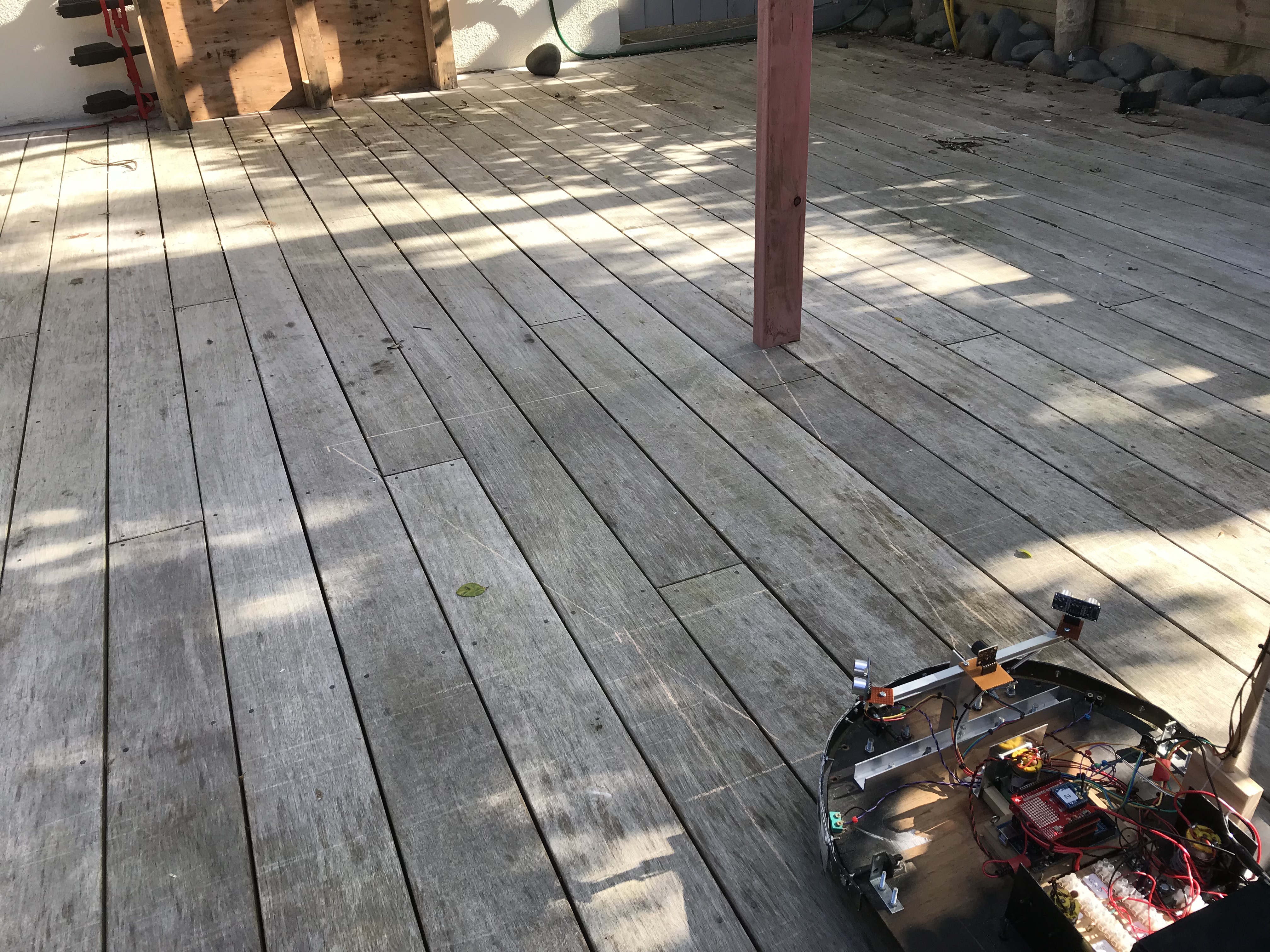
Time for some navigation tests. This sensor seems far better suited and I can only hope that it does not suffer from false triggering. The sensor will be soldered to the veroboard so it has a more stable base. This might bring it too close to the top of the tower mount so it might be necessary to modify that slightly if this causes problems.
May 2018
| Home | Contents | Start | Prev | 1 | 2 | 3 | 4 | 5 | 6 | 7 | 8 | 9 | 10 | 11 | 12 | 13 | 14 | 15 | 16 | 17 | 18 | 19 | 20 | 21 | 22 | 23 | 24 | 25 | 26 | Next |