| Home | Contents | Start | Prev | 1 | 2 | 3 | 4 | 5 | 6 | 7 | 8 | 9 | 10 | 11 | 12 | 13 | 14 | 15 | 16 | 17 | 18 | 19 | 20 | 21 | 22 | 23 | 24 | 25 | 26 | Next |
Adding Radio Control
Update 01-10-2021I have been using the mower to take photos of grass. Everything works fine and I collected about 1000 images. The problem is getting images of 'not grass'. Concrete and pavements are ok, but in order to capture the inside of a bush involves me climbing into the bush with Moana and a laptop. I can't get many photos this way and I've been getting some strange looks from the neighbours. I need a better plan.
Wheels Revisited (again)
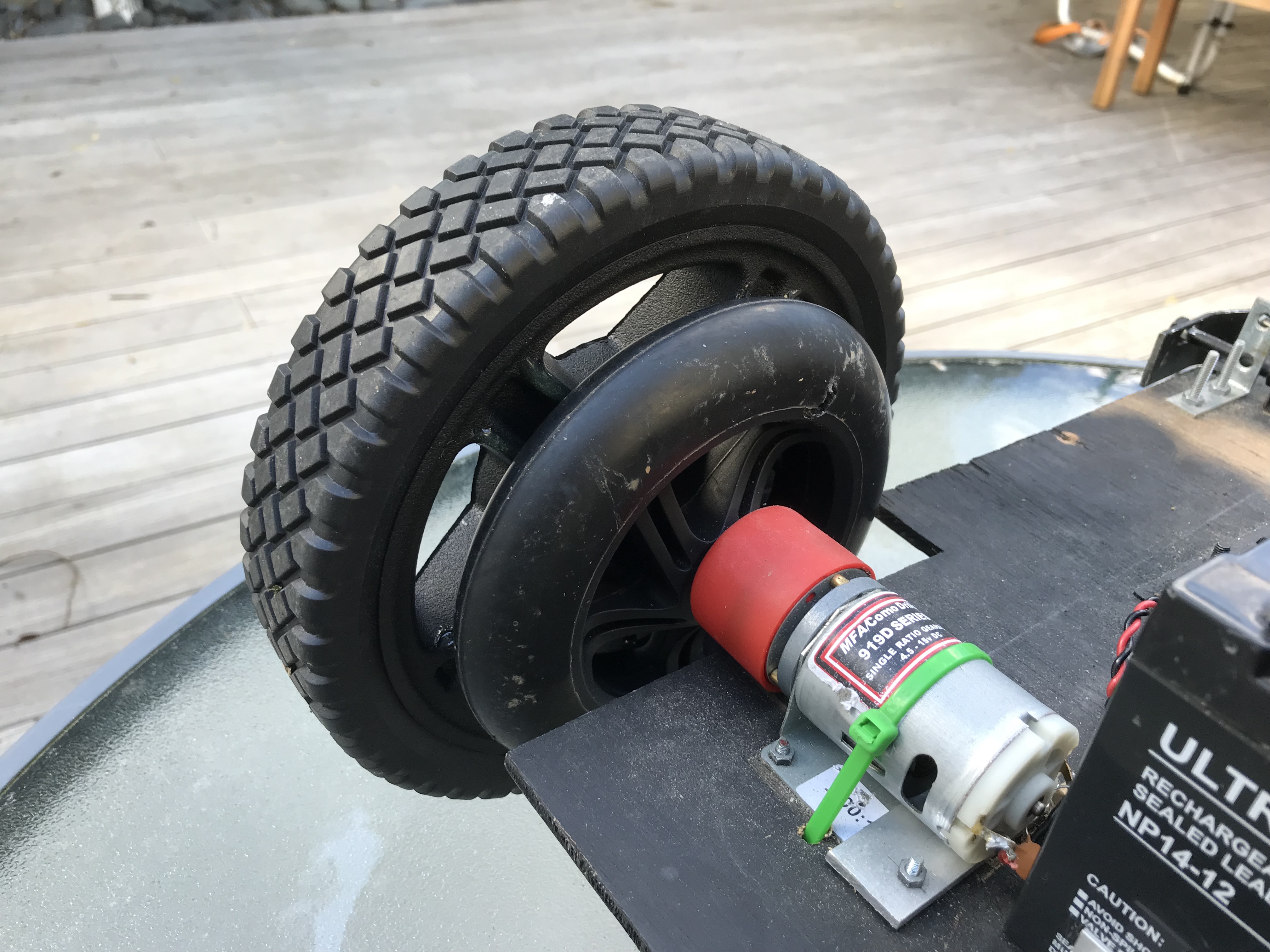
One problem is the locomotion wheels. Although ok for grass, when it comes to gravel, roots, bark etc, they dont really cut it. So the first thing to do is upgrade the wheels yet again. As we were in a second lock-down, I was quite limited for choice but lawnmower wheels seemed to be an 'essential item' so I bought some on-line which have an 210mm diameter and better grip. I knocked the bearings out and epoxied these onto the original wheels as a stopgap, but this seemed to work quite well so I've not done anything further.
Integrating Radio Controls with Arduino
I was thinking it would be really useful to remotely control the mower so I can drive it in and out of bushes without needing to dive in there myself. Hopefully, this will speed up my image capture process as it will take ages otherwise. Rather than modifying my Xbee link and adding a joystick, I thought I could use a radio control transmitter (as used to control planes and drones) to steer the mower and hopefully enable/disable the camera remotely. Further research shows that RC transmitters also support telemetry back from the model. I will need to work out how to do this later but for now, I need to work out how to integrate radio control with the autonomous lawnmower.
RC transmitters support several channels. I reasoned that I need at least two joystick channels (throttle and steering) but it would be very useful to have multiple switch channels to control features on the mower (eg camera enable, kill motors, turn on distance sensor etc). I bought an 8 channel transmitter which may be an overkill but I reasoned that I can reuse the transmitter on several projects so having room for expansion is worthwhile. And when I work out the telemetry side, I should be able to send status text and codes back to the transmitter.
Since radio control models are full of servos, the RC receiver outputs PWM signals, one per channel so it is possible to use pulseIn() to measure the pulse width. This ranges from approximately 1000uS to 2000uS at extreme ends of the joysticks (measured on an oscilloscope). This is a whole new world for me and it took a little time to learn about radio controlling models. However, once I understoold the binding to transmitters, I wired one channel up to an arduino, used pulseIn() and all worked fine.
However, when using multiple channels, pulseIn() did not work as it is a blocking call and you need to know the sequence the channels are decoded. I decided to write an interrupt library to overcome this and after some fine tuning it works well, being extensible from one channel up to 8. I am currently using 4:
- Forwards and backwards (proportional)
- Left and right (proportional)
- Kill motors (two position switch - a safety feature)
- Manual/autonomous mode
- Turn camera on and record images
These last two are on a three position switch. A three position switch essentially gives you two controls on a single channel.
The Radio Control Library
I wrote this as a arduino library since it will be useful on a multitude of projects. The only requirement is that you need to connect the PWM outputs from the RC Receiver to an arduino pin that supports interrupts. This limits your choices on an UNO (onluy 2 pins) but on an ardiono Mega, there are many to choose from. However, as most projects are on a UNO, I used the PinChangeInterrupts library as well, so extra interrupts can be use on a UNO.
I don't usually dump all the code in the documentation but this library is a little unusual as it uses interrupts so this is in case I need to recall it later. The code, examples and keywords.txt are in the RadioControl subdirectory under the libraries directory (under arduino home). You can then include the library using the Arduino IDE library manager.
RadioControl.h
/** * Test to read multiple control channels. Pulsin does not cut it so we need to use interrupts. Since * the UNO only has two interrupt pins, we use a library to allocate a hardware interrupt to specified * pins. * Note that if using PinChangeInterrupt library, you need to be on a port that supports * port interrups (eg on Mega, can use Analog A8-A15 but not the D30s). See PinChangeInterrupt * documentation. */ #ifndef RadioControl_h #define RadioControl_h #include |
RadioControl.cpp
  /**
   * Test to read multiple control channels. Pulsin does not cut it so we need to use interrupts. Since
   * the UNO only has two interrupt pins, we use a library to allocate a hardware interrupt to specified
   * pins.
   */
  #include "RadioControl.h"

  // These are populated by the isr so need to be global and volatile.
  volatile uint32_t start_time[8];
  volatile uint16_t pulse_width[8];
  volatile uint8_t statusFlags;

  static uint8_t CHANNEL_FLAGS[] = {1,2,4,8,16,32,64,128};
  uint8_t ip_pins[8];

  RadioControl::RadioControl(uint8_t pins[], uint8_t arrayLength) {
  	num_pins = arrayLength;
  	for (uint8_t i = 0; i < arrayLength; i++) {
  		ip_pins[i] = pins[i];
  		pinMode(pins[i], INPUT);
  	}
  }

  uint16_t RadioControl::readChannel(uint8_t id) {
  	return channel_pw[id];
  }

  void RadioControl::checkInterrupts() {

    if (statusFlags) {
        noInterrupts();
        status = statusFlags;

        for (uint8_t i = 0; i < num_pins; i++ ) {
      	if (status & CHANNEL_FLAGS[i]) {
            channel_pw[i] = pulse_width[i];
        	}
        }

        // clear down shared status byte
        statusFlags = 0;
        interrupts();
      }
  }

  void isr(uint8_t id) {
    if (digitalRead(ip_pins[id]) == HIGH) {
      start_time[id] = micros();
    } else {
      pulse_width[id] = (uint16_t)(micros() - start_time[id]);
      statusFlags |= CHANNEL_FLAGS[id];
    }
  }
|
RadioControlExample.ino
  #include "RadioControl.h"
  #include "PinChangeInterrupt.h"

  #define CHN1_PIN 8
  #define CHN2_PIN 9
  #define CHN3_PIN 10
  #define CHN4_PIN 11

  /**
   * Create an array of pins and pass the array into the constructor, along with the number of entries.
   * The library supports up to 8 different inputs. This example shows 4 inputs.
   * eg: RC(pinarray[], number_of_elements).
   * This can be the global namespace or the main loop.
   */
  uint8_t pins[] = {CHN1_PIN, CHN2_PIN, CHN3_PIN, CHN4_PIN};
  RadioControl RC(pins, sizeof(pins)/sizeof(uint8_t));

  void setup()
  {
    Serial.begin(9600);
    Serial.println("Multiple Channel Library Test");

    // attach interrupts to each of the pins. Reference a different interrupt service routine for each interrupts.
    attachPCINT(digitalPinToPCINT(pins[0]), isr_channel1, CHANGE);
    attachPCINT(digitalPinToPCINT(pins[1]), isr_channel2, CHANGE);
    attachPCINT(digitalPinToPCINT(pins[2]), isr_channel3, CHANGE);
    attachPCINT(digitalPinToPCINT(pins[3]), isr_channel4, CHANGE);

  }

  void loop()
  {
    /**
     * Each time round the loop, call checkInterrupts() and then
     * readChannel(i) where i is the pin index as above.
     */
    RC.checkInterrupts();

    uint16_t pw[4];
    for (uint8_t i = 0; i < 4; i++) {
      pw[i] = RC.readChannel(i);
    }

    for (uint8_t i = 0; i < 4; i++) {
      Serial.print("Channel[");
      Serial.print(i);
      Serial.print("]: ");
      Serial.print(pw[i]);
      Serial.print(" | ");
    }
    Serial.println();

    delay(200);
  }

  /*
   * Create an interrupt service routine corresponding to each interrupt pin. Each should
   * call the library ISR (called isr) and pass in the index of the pin (eg pin[1] calls isr_channel2() which calls isr(1)
   */
  void isr_channel1() {isr(0);}
  void isr_channel2() {isr(1);}
  void isr_channel3() {isr(2);}
  void isr_channel4() {isr(3);}
|
With Moana's pimped wheels, driving across dirt and into bushes was much easier. The radio control technology is very mature, it is possible to control the mower from hundreds of meters away. I managed to get over 1000 images in 30 minutes so my foray into Radio Control has been well worth the effort. Another couple of sessions and I should have respectible image set and then focus on selecting an appropriate ML agorithm.
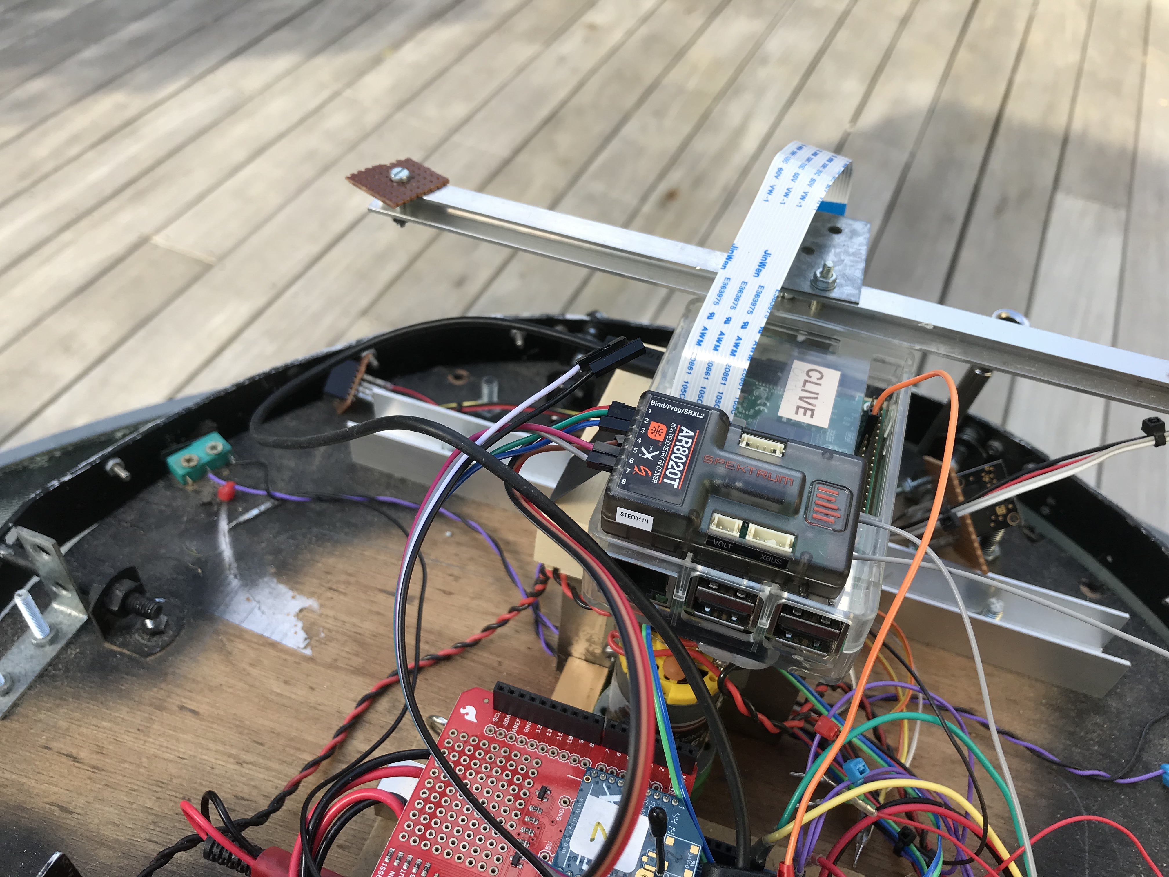
Here you can see the radio receiver mounted on top of the Pi
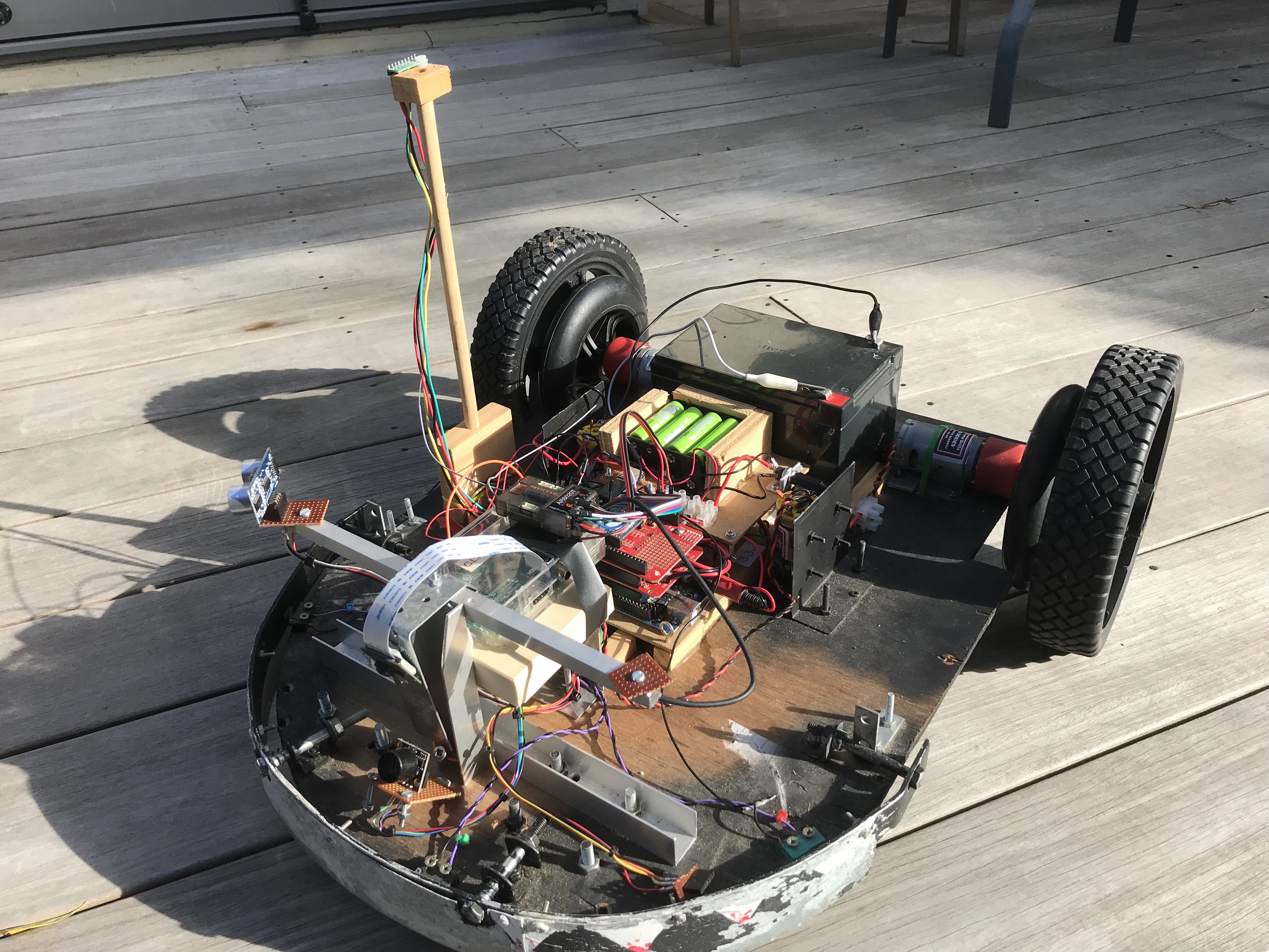
And this is moana ready for some off-grass image collection.
Maybe a small video here of moana being driven to collect photos
Sepember 2021
| Home | Contents | Start | Prev | 1 | 2 | 3 | 4 | 5 | 6 | 7 | 8 | 9 | 10 | 11 | 12 | 13 | 14 | 15 | 16 | 17 | 18 | 19 | 20 | 21 | 22 | 23 | 24 | 25 | 26 | Next |