| Home | Contents | Start | Prev | 1 | 2 | 3 | 4 | 5 | 6 | 7 | 8 | 9 | 10 | 11 | 12 | 13 | 14 | 15 | 16 | 17 | 18 | 19 | 20 | 21 | 22 | 23 | 24 | 25 | 26 | Next |
Compass Revisited
Moana has been slowly growing in complexity and quite a few sensors are now installed and wired up. During testing, I noticed that the robot was not turning to the specified angles, but only occasionally which was puzzling. I persevered with the compass for many hours but found I could not get it behave reliably. When I tested the module off the mower, I could see the same problem. It went for a time being reliable, then it seemed to give erroneous readings. After buying a replacement module, using a dedicated level shifter, paring back the software, I was not making much progress.
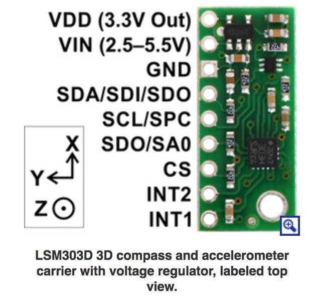
The LSM303D Compass Module
In order to move forward, I decided to change to a different type of compass module. I had spent a lot of time tweaking the code for this IMU and it is frustrating things have stopped working but I needed a plan. So I 'downgraded' to a dedicated compass module, the LSM303D. This package contains a magnetometer and an accelerometer (no gyro) but the magnetomer is tilt compensated automatically by the accelerometer. So this device will be better for mowing on slopes (without the need for additional processing). The device has a 3.3v regulator on board but can be run from a 5v supply which meant I needed no level-shifter on the I2C lines.
Wiring the Compass Module
The LSM303D uses the I2C bus (SDA and SCL) which are pins 20 and 21 on the arduino Mega.
In the lab, this compass proved to be very accurate (within a degree) and gave good results when tilted from the horizontal. The results were consistent so things were looking good. I will probably need to calibrate the compass later, but out-of-box, it is at least giving consistent results.
I installed it on Moana, after making all the appropriate software changes. The results were terrible. Moana weaved and oscillated and did not seem to be able to hold to a steered bearing at all well. After writing various compass test routines, I determined that the compass worked as expected, with a high degree of accuracy when the locomotion motors were not turning. When the motors were turning, the reading were haywire. I narrowed this down further. It was more accurate when the motors were turning but not rolling the mower (suspended above the ground), but it was still bad. This could be due to the compass tower vibrating, or the motors just needing to overcome unevenness in their path.
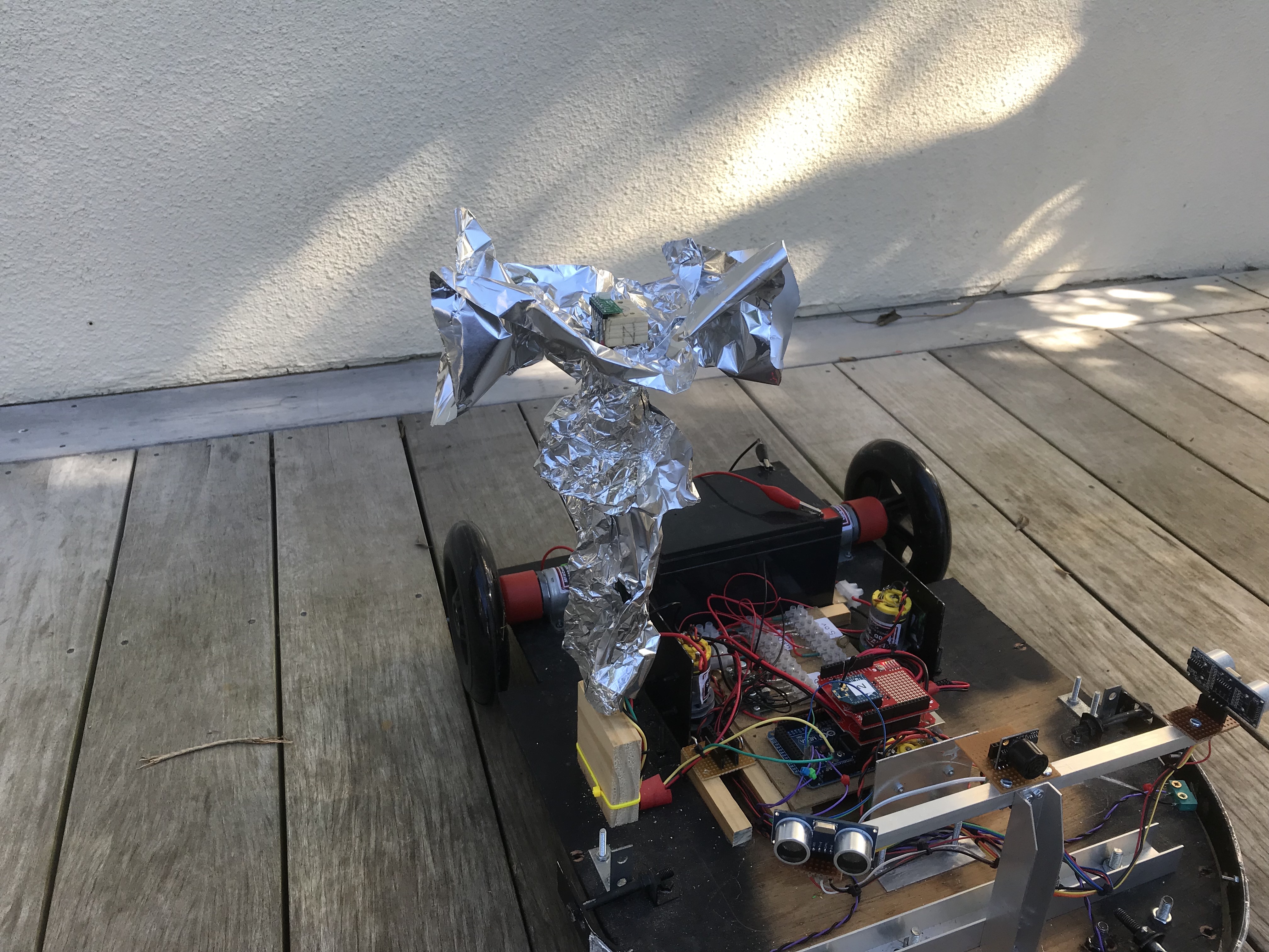
This could be due to electromagnetic radiation of spikes on the power lines. I tried to isolate the EM interference by wrapping the tower and the wires in tinfoil. This made no discernable difference.
I added extra capacitors across the 5V distribution line, (1000uF and 100nF). I also added a 100nF capacitor across the supply on the compass board. This improved matters, but not the accuracy I require. However, I believe I am onto something now.
I have two 12v 12AH batteries I swap in and out of the mower during testing. Investigation showed that one of thes batteries was not holding its charge as well as the other battery. It looked like it could not source the current required to drive the motors, they were driving ok but I don't think the supply is 'stiff' enough for the electronics. This is not a good place to be, you don't want the mower to go haywire as the battery slowly discharges, and it starts exhibiting this problem when the battery is in a relatively good charge state. As batteries age, they will cause problems.
So I have a plan, I either need to replace the battery with a new one, move to better battery technology (eg Lithium), or split the supply. I had considered splitting the supply early on, but assumed the voltage regulator modules I had used would isolate the electronics from the vageries of the motors.
To prove my theory, I aim to use a 9v NiMH supply to drive the arduino and voltage regulators. All the sensors will use this supply. The 12V SLA will only drive the motors. If we can isolate the power and the earths, that would be even better, I guess it depends on how the Motor Driver isolates the earths.
Adding NiMH Batteries
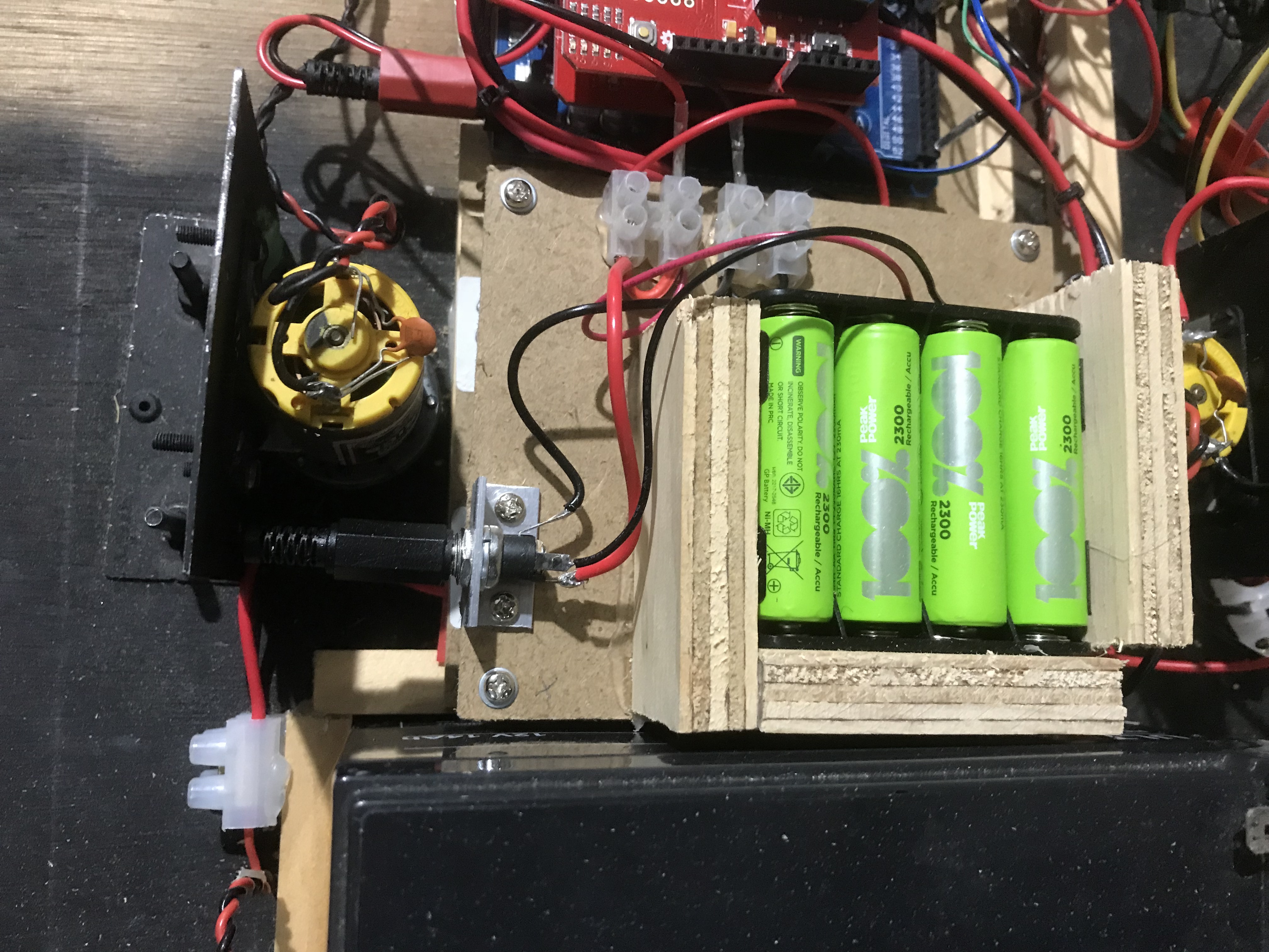
I rewired a few things. The choc-block power supply board is proving to be very useful. I decided the 12V supply would only feed the Motor Driver board (and later, the cutting motors). All the Electronics would be fed from a seperate NiMH supply made up of 8 AA cells. These would supply 9.6V which would feed the arduino, and then onto the regulators to provide seperate 5V and 3.3V supplies.
No matter how much room you think you have on a robot, it is never enough. I've had to make a sandwich layer over the power distribution board to mount the batteries. If this solves my compass problems, I will add a socket for recharging and a relay that disconnect the battery pack when the main 12V supply is disconnected. Initially, being able to take the battery pack out easily is useful but I may move the batteries to the lower layer and how the power distribution layer on top later.
So here is the extra battery pack layout. It meant changing a few things on the distribution board so we now have a 12V, 9v, 5v and 3.3v selection. I wired the power socket so that when a 2.1mm plug is present, it connects directly to the battery and disconnects the batteries from the circuit so that the arduino and all the 5v and 3.3v sensors are turned off. This would be used for charging. Disconnecting the plug will switch them all on so at some stage, this needs wiring into an on/off switch. A job for another day.
The Verdict
Not really convinced this has made a difference. Actions taken:
- Disconnect everything else. The arduino now only powers compass, motor driver and Xbee.
- Put smoothing capacitors across arduino supply.
- Put smoothing capacitors across 12V supply.
- Shield wires to compass.
- Added/removed supply smoothing capacitor on the compass itself.
- Put a metal shield over the boards to reduce em interference.
The results of all these actions saw no real improvement, the compass was still giving out readings that were up to 90 degrees off, in a seemingly random order. I put an oscilloscope on the arduino power supply line and then those at the compass itself. I could see no noticeable spikes. I cannot see how it could be EM radiation as I have had this working fine before (admittedly with a different compass module), and all the other ancilliary circuitry has been disconnected.
A Theory - My Eureka Moment
I have tried to eliminate EM interference and interference on the power lines and am still seeing the problem. The only other thing I can think of is that perhaps the vibration on the compass mast is causing a problem. And then I understood. This new compass is tilt-compensated which means the accelerometer values will alter the output of the compass. When you hold it in your hand, this is a great thing to have as tilt is a potential problem. However, when on the compass mast, vibrations will cause the compass to whip backwards and forwards very quickly. This is essentially a high acceleration vector which may well cause large adjustments to the compass output. So, the solution it to take the compass off the mast to reduce the acceleration. So that is what I did, and the values read from the compass improved immediately, still not as good as when no motor is running, but much better. However, I found the bearing would not change significantly when turning, too much magnetic interference when in the 'electromagnetic swamp'. OK, so not a problem with the compass as such, but the application in which I am using it. This explains why the first compass was not affected the same way as although that had an accelerometer, it was not 'tilt-compensated'.
Compass Tests
I have collected test data here over a period of time. All the following tests are done with the mower under locomotion, powered by the 12V lead acid battery and all electronics via the NiMh battery pack.
Compass on the mast
Compass setup done
Setpoint: 229
GO
Received: com
com
Heading: 228
Heading: 208
Heading: 156
Heading: 88
Heading: 238
Heading: 134
Heading: 278
Heading: 262
Heading: 240
Heading: 246
Heading: 190
Heading: 287
Heading: 205
Heading: 251
Heading: 206
Heading: 249
Heading: 209
Heading: 233
Heading: 248
Heading: 209
From the above, we can see this is not good. The bearing can be 130 degrees out and there are outliers that are even worse. This is not a viable option.
Compass on the Deck
Compass setup done
Setpoint: 278
GO
Received: com
com
Heading: 277
Heading: 272
Heading: 274
Heading: 273
Heading: 281
Heading: 278
Heading: 275
Heading: 276
Heading: 275
Heading: 279
Heading: 279
Heading: 280
Heading: 279
These look much better, 7 degree accuracy. However, I found that I could turn the mower through 90 degrees and it would still read 270. If fact, the bearing became stuck at around this value so its accuracy is pants, its not a compass at all! So although it looked promising, this is not a viable option.
Compass on the mast without accelerometer compensation
I hacked the LSM303D library. I could not easily see a way to disable the accelerometer so I wrote a new method getHeading_uncompensated() that used the raw X, Y magnetometer readings and calculated the bearing from them. These are the results:
Non compensated:
Received: mo2
mo2
Heading: 49 , delta: 1
Heading: 47 , delta: -1
Heading: 47 , delta: -1
Heading: 47 , delta: -1
Heading: 47 , delta: -1
Heading: 47 , delta: -1
Heading: 46 , delta: -2
Heading: 47 , delta: -1
Heading: 46 , delta: -2
Heading: 46 , delta: -2
Heading: 46 , delta: -2
Heading: 47 , delta: -1
Heading: 45 , delta: -3
Heading: 46 , delta: -2
Heading: 47 , delta: -1
Heading: 44 , delta: -4
The compass responded to the robot being turned and it always kept within 5 degrees of the setpoint. So after a house of pain, I see the accelerometer compensation is the bad-boy that has caused me so much trouble with the LSM303D. I may be able to use it with a substantial shock-mounted tower, but disabling the compensation is the key.
Compass on the mast without accelerometer compensation and added averaging
Since the compass has quite a high query rate, I decided to average three readings to see if I could improve accuracy.
Heading: 50 , delta: 0
Heading: 50 , delta: 0
Heading: 50 , delta: 0
Heading: 50 , delta: 0
Heading: 50 , delta: 0
Heading: 50 , delta: 0
Heading: 49 , delta: -1
Heading: 50 , delta: 0
Heading: 49 , delta: -1
Heading: 49 , delta: -1
Heading: 48 , delta: -2
Heading: 49 , delta: -1
Heading: 48 , delta: -2
Heading: 50 , delta: 0
Heading: 49 , delta: -1
Heading: 49 , delta: -1
Heading: 49 , delta: -1
Two degree accuracy. That is more than acceptable. This has been a long and painful journey so I hope others benefit from my mistakes! I now have a robot with a split supply. I don't know if I really need this, but it certainly wont do any harm so I will continue with it. It is time to add all the sensors back in and get the Moana back to the state she was a couple of months ago.
Note: The LSM303D has been discontinued. I believe it can replaced by the LIS3MDL which is pin compatible. It has no accelerometer so if I need to adopt it, I wont be necessary to hack the library! It also has a voltage regulator onboard like the LSM3030M
August 2018
| Home | Contents | Start | Prev | 1 | 2 | 3 | 4 | 5 | 6 | 7 | 8 | 9 | 10 | 11 | 12 | 13 | 14 | 15 | 16 | 17 | 18 | 19 | 20 | 21 | 22 | 23 | 24 | 25 | 26 | Next |